This thread has been locked.

If you have a related question, please click the "Ask a related question" button in the top right corner. The newly created question will be automatically linked to this question.

ADS122C04: 50/60 hz rejection with different sampling frequencies

Part Number: ADS122C04

Hi,

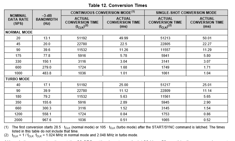
I found this graph in the datasheet. since the -3db line moves with the sampling frequency. does it affect the 50/60Hz rejection drastically?

Regards,

Tony

  • Hi Tony,

    In section 8.3.5 on page 26 of the ADS122C04 datasheet shows the filtering graphs for the various data rates.  You will notice that 50/60 Hz rejection can only take place at 20sps data rate.  The 20sps data rate for 50/60 Hz rejection is mentioned several times throughout the datasheet including the first page of the datasheet.

    Best regards,

    Bob B

  • Hi Bob, 

    Thanks for the Info.

    Could help me understand what can be done if I want a better 50/60Hz rejection even at higher sampling rates?

  • Hi Tony,

    For the ADS122C04, all data rates above 20 sps have 50 and 60 Hz within the passband of the device.

    The best thing you can do is to prevent the 50/60 Hz from entering your board. In many cases these frequencies enter on sensor cabling. Using shielded cables with proper termination is one method of reducing the power line-cycle noise. You want to keep this noise low as any gain stage will gain up the noise.

    You can also improve the noise reduction by making your analog input filter more aggressive. The benefit here is that you again reduce the noise before the gain stage of the ADS122C04. The downside is any change in the sensor output is reflected more slowly to the ADC input due to the increased analog settling.

    Another possibility is to use averaging so that the data rate divided by the number of averages is near the 10 so that notches are created at 50 and 60 (10 Hz and harmonics). There are a couple of considerations to think about. One consideration is the ADS122C04 does not output a data rate where you can divide a integer value to get exactly 10. See Table 12 on page 28 of the datasheet. The data rates are nominal values and not exact. This means the notches will be a little off so that attenuation will be there but not necessarily at the exact frequencies desired. The second consideration is that it takes time for the digital value to settle through the filter. If you have a moving average filter it will take time for the data to pass through from one end of the filter to the other. So any change at the ADC input will also take time to be seen on the output.

    For some applications, like a weigh scale, it may make sense to monitor the result for a significant change at a higher data rate (1000sps for example) and then as the output appears to settle the ADC is switched to 20sps for a more accurate measurement.

    Best regards,
    Bob B
  • Thanks Bob for the Info, it was very useful.