This thread has been locked.

If you have a related question, please click the "Ask a related question" button in the top right corner. The newly created question will be automatically linked to this question.

ADS1299: Board testing troubles

Part Number: ADS1299

I am using the ADS1299 Evalution Module and have been trying to test the board using a 10mV, 50Hz sine wave generated by an ECG generator. Im feeding the signal through channel one (Pin 34 and 36 of J6) and putting my reference on pin 6 of JP25. The jumpers are set to factory. The output im getting looks like all noise, attached below:

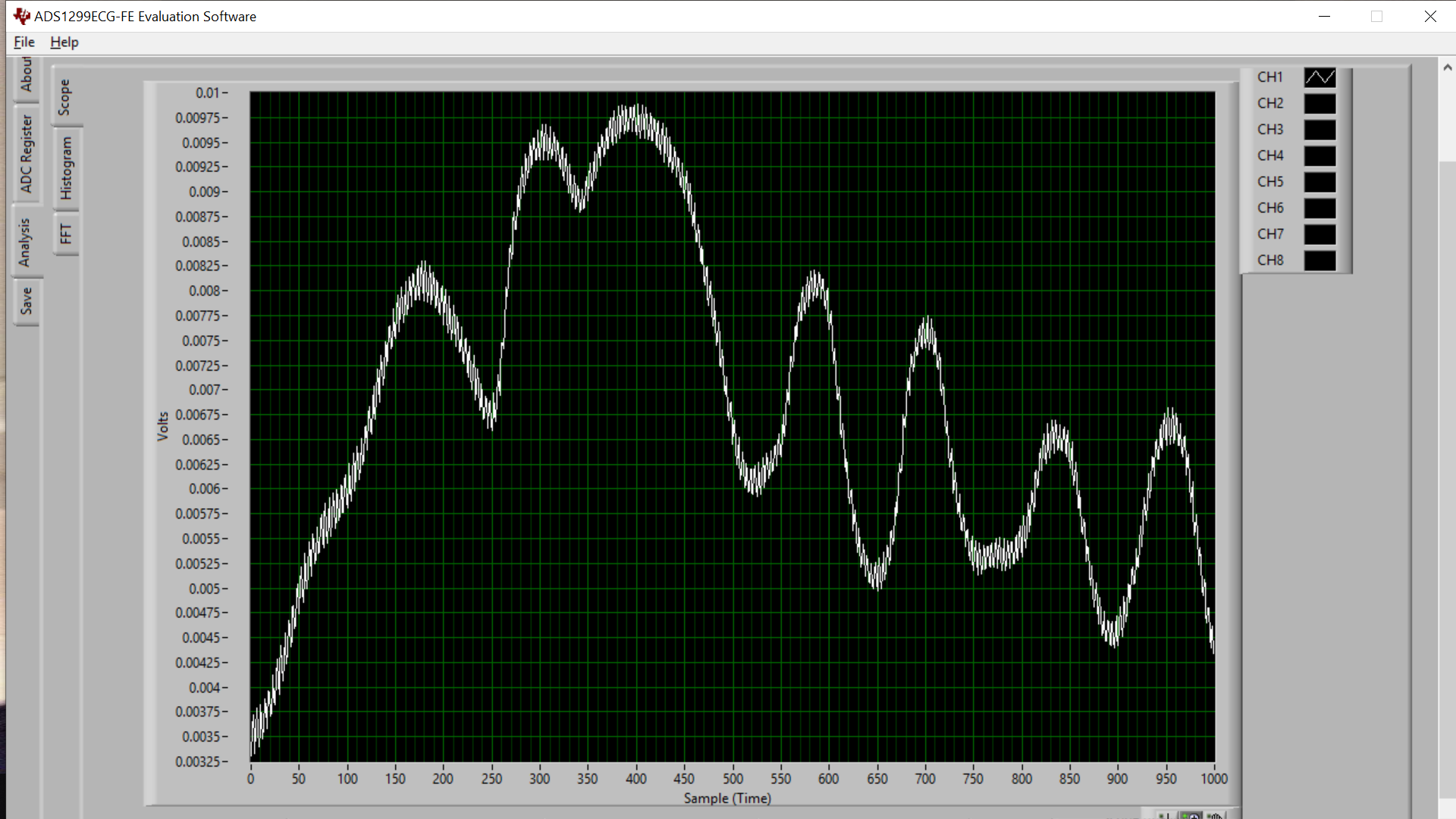
What could the issue be? How can I resolve it?

  • Hello Reza,

    Thank you for your post and welcome to our forum!

    Please refer to Figures 20 - 22 in the ADS1299 datasheet to make sure you have the correct input signal configuration. You will need to ensure that the common-mode voltage (VCM) is set appropriately by your signal generator (typcally near mid-supply) and that the ground of the signal generator is shared with the EVM.

    If you are applying the signal to IN1P and IN1N through the header pins on J6, then you will not need the reference electrode connection as you are not using the SRBx pins.

    Best regards,