This thread has been locked.

If you have a related question, please click the "Ask a related question" button in the top right corner. The newly created question will be automatically linked to this question.

TSW1400EVM: Problems to capture data from HSDC as doing undersampling

Part Number: TSW1400EVM
Other Parts Discussed in Thread: ADS62P49

Hi,

I am capturing data using TSW1400 and TSW4200ADC (ADS62P49) with external clock.

Is there anyway to capture digitized data from HSDC Pro with undersampling? i.e 250 MHz CLK and Anaglog input 352 MHz.

Cause in the HSDC PRO you can only capture data like this.

Any suggestion from you to capture data with undersampling?

Thank you

L.
  • Long,

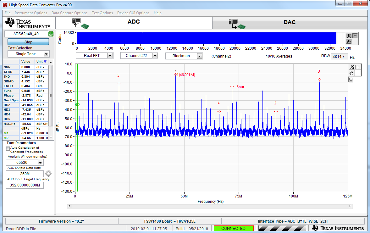
    The input to the ADC is to large and is saturating the device. The parameter called "Fund." in the left side of the GUI is showing the fundamental power. This is your input tone and this value needs to be -1.0dBFs or less. Your reading above is 0.945. I suggest you lower the input amplitude until this value is at -1.0 dBFs or less. 

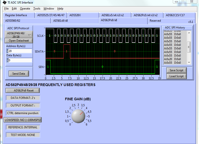
    Also make sure to disable the low speed mode by setting bit D2 to "0" of register 0x20.

    Regards,

    Jim

  • Hi Jim,
    You mean the D2 of register 0x20 of TSW1400.
    What about capturing pulsed RF signal with external trigger? I havent seen any document regarding this.
    Long
  • Long,

    Yes, bit D2. Before we start discussing capturing pulses, did lowering your amplitude of the IF help with the capture?

    Regards,

    Jim

  •  Hi

    yes I did. However, I could get -1 dBFS at fundamental frequency even I lowered the amplitude input down to -20dBm. Before it was -2 dBm.

    Any suggestion to explain why?

    L.

  • Not sure what you are saying. Can you send a screen shot of the HSDC Pro capture with the fundamental at -1dBFs.

  • Hi,

    Sure. I think the input amplitude is OK now.

    Can you instruct me to capture RF pulsed i.e 300 MHz with 14 Hz Pulse period, 3.5 ms pulse width.

    I am gonna use the pulse to trigger the TSW1400.

    L.

  • 4530.slwu087d.pdfLong,

    See section 3.1.3.3 of the attached User's Guide.

    Regards,

    Jim

  •  Thanks Jim,

    I have anther question to be solved. I am observing the data in time domain with external trigger.

    However, I wonder how I can capture the envelope signal during 3.5ms of the pulse. Or when the trigger is ON, it starts capturing till the next trigger. In my case, I got 300 MHz signal during only 260 us.

    How I supposed to set up to capture the envelope during the trigger event. 

    Do you have any suggestion?

    L.

  • Long,

    The GUI only allows you to trigger on one event and captures the number of samples specified under the "Captions Option" tab which is under the "Data Capture Options" tab in the GUI setting.

    Regards,

    Jim 

  • Hi,
    Last question for this topic. Do you have any document in order to read raw data from ADC in bin format as using TSW1400 in Matlab?
    I am very much appreciated if you share the script to have access to the file.
    L.
  •  Hi Jim,

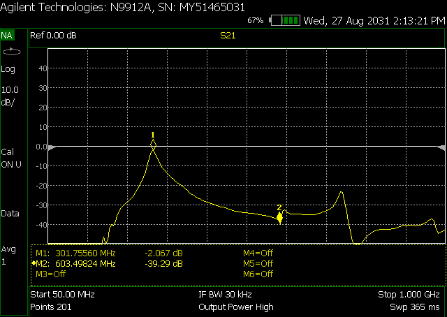
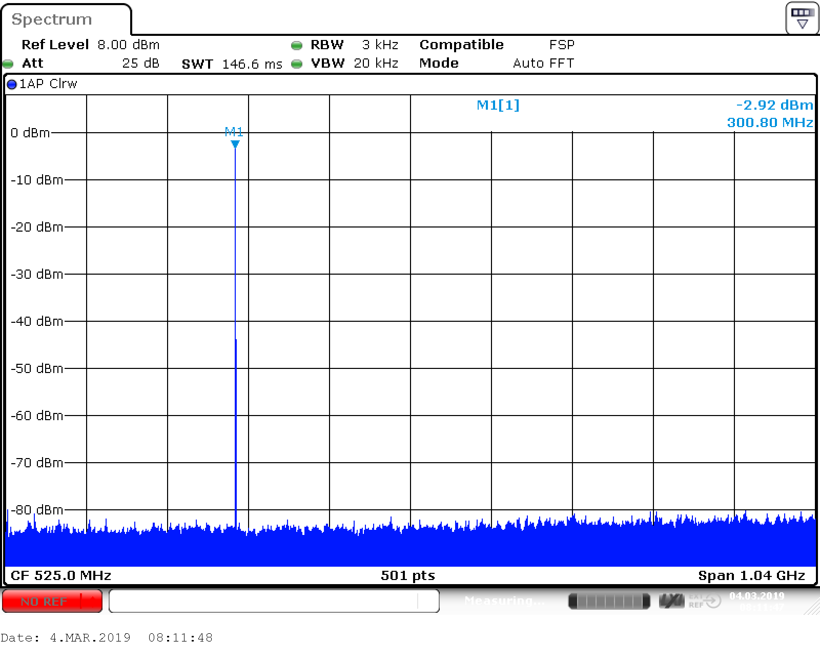
    I have one thing to ask about the captured signals by TSW1400. I have 300 MHz input signal, it then goes through bandpass filter (few MHz bandwidth) as in the attach.

    The sampling freq is 250 MHz, however, i cannt explain why I got 100 MHz signal out there on HSDC PRO. Its amplitude is very large.

    Any explain or anything wrong with the ADC.

    Thank you

    L.

  • L,

    This is the second and third harmonics (600MHz, 900MHz) of the fundamental. I am guessing you need a better bandwidth filter for your 300MHz signal. Attached is a view of a 300MHz BPF we normally use from TTE. When using this, the signal at 100M is down about 75dBFs. You may also want to change your frequency so that it is either a little above or below 300MHz so that HD2 and HD3 do not fall on top of each other at 100MHz. Doing this will lower this spur to below -80dBFs.

    Another option would be to change the sample rate a little above or below 250MHz.

    Regards,

    Jim

  • Hi Jim,

    I am using a new BPF which has similar performances. However, the harmonics are still high.

    Is there any problem with the ADS62P49, which offers superior performance as provided in datasheet?

    If no problems happen at ADS62P49, is there any cause from the external clock???

    I have attached the BPF frequency response and a capture of HSDC PRO at 352 MHz (250 MHz Fs).

    Thanks.

    PS: I am using LVDS output, I guess there is any problem as using LVDS or CMOS output right?

  • Long,

    As I mentioned before, you must keep your fundamental power below -1dBFs or you will start saturating the ADC. Above, your fundamental is at 1.96dBFs. You need to back this off at least 3dBs. Once you get this all under control, I suggest you use an input frequency that is shown in the data sheet and compare your results with the data sheet. You should be able to get at least the typical values shown in the data sheet. If not, then one reason for this would be a noisy clock source. If this is the case, find a source with better phase noise performance and maybe use a filter for the clock input. Other issues could be a noisy analog input source and/or power supplies. I am guessing your main problem is your input power is to high.

    Regards,

    Jim 

  • Long,

    Reading raw ADC data directly using Matlab will be available in next HSDC pro release which is expected in a month time frame. 

    For now we recommend using 'save raw data to file' API that will save a CSV file with the ADC data.  

    Regards,

    Jim

  • Hi,
    I wonder about the analog input power the chip can handle about typical 2 Vpp (equivalent to 10 dBm). I am injecting -40 dBm to get fundamental power below -1 dBFs.
    What do you explain about this?

  • Long,

    Is there a chance you have the ADC setup for 2's compliment? The TSW1400 is expecting unsigned binary data. This may be your problem.

    Regards,

    Jim 

  •   Hi

    Definitely it is the problem I have changed to binary. However it is unstable somehow what do you think?

    Sometimes the captured data looks very goood and sometimes it looks bad.

    Can you explain the reasons? And you can see the change in the ADC value at each case.

    L

  • Long,

    It may be related to your narrow pulse. Is there a way to synchronize this pulse with the sample clock? Another option is to use the trigger function of the TSW1400 and adjust this trigger point with delay settings until this capture becomes stable. One test you can try is to increase the pulse width to see if this makes the setup more stable.

    Regards,

    Jim

  • Hi,
    Still it doesnt work out with longer pulse. I even changed R&S signal generator, it is still problematic.
    It happens periodically. One capture is OK the next capture is bad.
    I will try to lower the rise time of the pulse it might help.
    Anyway, I can close the topic and thanks so much for help.
    L.