This thread has been locked.

If you have a related question, please click the "Ask a related question" button in the top right corner. The newly created question will be automatically linked to this question.

ADS131E04: strange DRDY behavior

Part Number: ADS131E04

Hi everyone,
I apologize in advance for the length of this post but I think it's better to say something unnecessary than omit something useful.
We are trying to use an ADS131E04 and a STM32F4 microcontroller on our custom board to acquire data from a 3-axial analog accelerometer but we are experiencing some strange behaviour of the DRDY line.


All we need is 100Hz sampling rate so we are planning to configure the ADC to 1kSPS, RDATAC mode, software START and STOP commands (the START pin is tied low), and just ignore 9 out of 10 DRDY transitions.
We are able to communicate with the ADS, correctly write configuration registers and read them back.

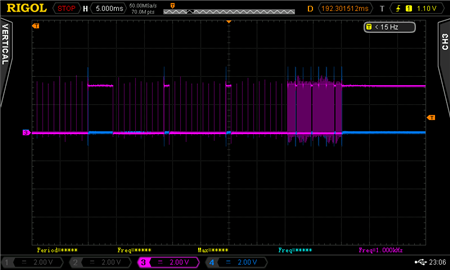
Now, as you can see from the first screenshot, when we issue a RDATAC command followed by START command, DRDY behaves correctly: there's a transition every 1ms (the line stays down because we're not retrieving data from SPI hence we're not issuing SCLK); but if we try to read the data (15 byte SPI read operation) then sometimes DRDY appears to slow down to one transition every 4.5ms (2nd screenshot).
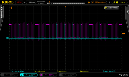

In the 3rd screenshot you can see the timing of DRDY (3-magenta), ISR semaphore unlocking (1-yellow) and SPI 15bytes read operation (2-cyan); just ignore number 4 (blue), I forgot to disable the line before taking the screenshot..
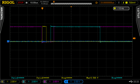

The retrieved data seem to be correct (in the sense that they follow the orientation of the sensor) so probably the problem regards just DRDY timing.The strange thing is that it doesn't seem to be precisely reproducible, it seems to have some kind of randomness because sometimes DRDY just stops "toggling" without issuing the STOP command.

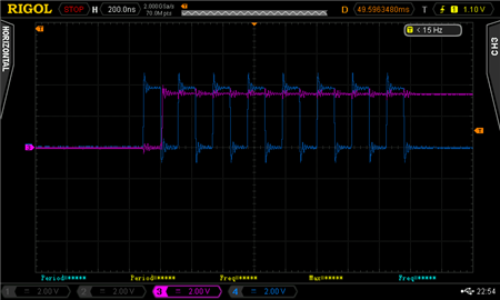
The 4th screenshot shows that when this happens, in the last acquisitions DRDY "toggles" at 16kHz instead of 1kHz (a kind of reset?! but the datasheet states that the module resets at 32kHz..).

If we try to read the configuration registers multiple times after DRDY stops, we see random values for few times and then some values that seem to be a "default" configuration.

Our configuration	Random values		"Default" configuration
0: 0xD0			0: 0x30			0: 0xD0
1: 0xD6			1: 0x4D			1: 0x91
2: 0xE2			2: 0x62			2: 0xE0
3: 0x61			3: 0x1D			3: 0x41
4: 0x00			4: 0x4E			4: 0x00
5: 0x10			5: 0x20			5: 0x10
6: 0x10			6: 0x76			6: 0x10
7: 0x10			7: 0x6C			7: 0x10
8: 0x90			8: 0x32			8: 0x10
9: 0x00			9: 0x00			9: 0x08
10: 0x07		10: 0x00		10: 0x07
11: 0x0F		11: 0xC0		11: 0x0F

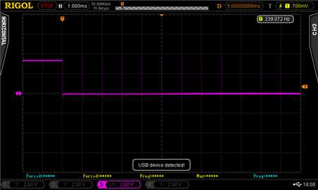
The last screenshot is just to show that DRDY goes correctly high after the first SCLK falling edge.


We tried different configurations (sampling rates, spi speed...) without any result.
Have you ever experienced something like this? If it can be useful I can upload the part of the schematics regarding the ADS.

Thank you in advance for your help.

Best regards.

Mattia

  • Mattia,


    Thanks for your writeup. I appreciate having a bit more information to help debug problems that come up.

    I think there's some problem with the communication with the device, but I'm not sure of all of it yet. I'll explain some of the things I'm seeing, and I'll suggest something to try.

    First, this ADC has some latency and the first conversion takes extra time to get a data that is fully settled. Normally I would have expected the START and STOP commands to start the ADC converting, and the STOP command to stop the ADC conversion. In your case, it looks like the conversion continues, because the /DRDY continues to come out once each 1ms. If you're doing this every 10ms to get data at 100SPS, I not sure why the ADC doesn't ever seem to stop.

    Second, the 4.5ms interval is expected. However I would have expected this to happen each time. If you use DR[2:0], then the data rate is 1kSPS when converting. However with the latency of the digital filter (or really the settling time of the first reading, the first reading comes out much later (and subsequent readings come out at 1/(data rate). You can see this on page 28 of the datasheet in the section on settling time. With DR[2:0]=100, the setting time of the first reading is 9224 tclk, at a clock of 2.048MHz, this is 4.5ms.

    If you're in RDATAC mode and try to read the registers, you might get the data out instead of the register data as soon as /DRDY goes low. I think that's why your RREG is giving bad readings.

    If you use the START and STOP commands, you could do something like you see in Figure 33 (page 29 of the datasheet), I would just do a single START and STOP to get only one data. From your plots, it looks like the STOP never comes up, but you do occasionally get the START.

    As for the DRDY toggling at 16kSPS, it does look like you're getting to a different data rate and while RESET will do that, I think this would be the wrong data rate for a reset unless the master clock was slower.

    For now this is what I would recommend. First, I think there may be some communication problems. Verify the digital timing and check SCLK frequency. It seems like you're missing STARTs and STOPs, but it's not clear to me exactly why that's happening. I'd also check for a RESET (make sure that /RESET is always high).

    To get data from the device, I would suggest an alternate communication method. First set the device to 1kSPS as you already have done. Then send an SDATAC command. This will prevent the data from updating to DOUT every time there's a conversion. However the device should continue converting. This should clear up the RREG problem.

    After that, to read out data, I would just use a timer from the microcontroller. Every 10ms, issue an RDATA command and then collect the data. This way the ADC doesn't start or stop, but you just collect data every 10ms. I think this would be the best way to get data for your application.

    Let me know what you think. I'm not sure I covered everything in your post.


    Joseph Wu
  • Hi Joseph,
    thank you for the quick response! "Unfortunately" today I'm not at work but first thing on monday I'll try your suggestions and let you know.

    Have a nice weekend!
    Mattia
  • Mattia,


    I haven't heard from you for about a week and I just wanted to check on your method of reading the ADS131E04. I had mentioned an alternate method of operation to read back the device. I would also note that I thought that you might have some communication errors because of the inconsistent response to the START command. I think that you may need to review the communications and verify there isn't noise causing problems. Regardless, I thought that the continuous operation with SDATAC, and a periodic RDATA would work to get what you wanted.

    I'll close this post for now, but if you continue to have problems, post back and we can continue to debug your circuit.


    Joseph Wu
  • Joseph,
    thank you very much for your support, it's very appreciated!
    Unfortunately we had some other issues at work so I've not been able to work on this until today. I hope I can post back in a couple of days to check your suggestions. For now SDATAC and RDATA with the 10ms timer works well so I'm signing this as "resolved", but I think some additional work is needed to properly understand why we have this strange behavior.

    Thank you again.
    Mattia
  • Hi Joseph, hi everyone,

    I'm writing again because I finally found out what the problem was.

    It was totally "my fault", the ADS131E04 behavior was right, I was looking in the wrong direction to find the problem and off course it took some time to realize that.

    As I said in my first post I am developing an application for STM32F4 microcontroller and I'm using the Hardware Abstraction Layer Library for SPI communication.  This library has a function called HAL_SPI_Receive()

    HAL_StatusTypeDef HAL_SPI_Receive(SPI_HandleTypeDef *hspi, uint8_t *pData, uint16_t Size, uint32_t Timeout)

    that, in spite of its name, actually transmits data while receiving. It uses a lower layer function called HAL_SPI_TransmitReceive()

    HAL_StatusTypeDef HAL_SPI_TransmitReceive(SPI_HandleTypeDef *hspi, uint8_t *pTxData, uint8_t *pRxData, uint16_t Size, uint32_t Timeout)

    that sends "dummy data" on the TX line just to generate clock pulses in order to clock out the data from the slave. In HAL_SPI_Receive() there is this line 

    HAL_SPI_TransmitReceive(hspi,pData,pData,Size,Timeout);

    so basically HAL_SPI_TransmitReceive() sends the content of pData on the TX line while receiving data on the RX line and saving them in pData. I think that somehow some of the data sent while receiving could contain a SDATAC command or a RESET command or something like that. So all I had to do to solve the issue was to reset the buffer to 0x00 before using it in the receive function.

    I hope that this can spare some time to anyone that experiences this problem.

    Again thank you Joseph for your time.

    Mattia

  • Mattia,


    Thanks for posting back with an explanation of the solution. I'm glad that you were able to figure out that problem.

    If you have any other questions on the ADS131E04, feel free to post back to this E2E forum!


    Joseph Wu