Because of the holidays, TI E2E™ design support forum responses will be delayed from Dec. 25 through Jan. 2. Thank you for your patience.

This thread has been locked.

If you have a related question, please click the "Ask a related question" button in the top right corner. The newly created question will be automatically linked to this question.

ADS124S08: ADS124S08 Design Review

Part Number: ADS124S08

Hi, I'm gonna use an ADS124S08 to measure 3 3-Wire RTDs. I'd be glad if you could check out my design. I will connect the RTDs according to the picture below.

These are my design parameters:

- AVDD 4.096V, AVSS 0V, Iex = 1mA, RTDmax = 153.58, Vref = 2.48V

Gain = Vref / (RTDmax * Iex) = 16.28 --> 16

Vcm = Vref + (RTDmax * Iex / 2) = 2.58V

AVSS + 0.1 + RTDmax * Iex * G / 2 < Vcm < AVDD - 0.1 - RTDmax * Iex * G / 2

1.33V < Vcm < 2.77V --> Vcm is ok!

Compliance Voltage is: AVDD - 0.6V = 2.7V

RTDmax * Iex + Vref = 2.63V < 2.7V --> Ok!

Fullscale utilization: n = 100 / Vref * (RTDmax * Iex) * Gain = 99.08%

Is my design correct or do you see any suggestions for improvement? Do I have to check whether the design also works with RTDmin? If I chose Vref = 2.5V, would I not need the reference resistor in my circuit because I can use the internal reference?

How do I design the input filters?

Kind regards

Cyrill

  • Hi Cyrill,

    Welcome to the E2E forum.  You may find some helpful information in the TI application note A Basic Guide to RTD Measurements:

    http://www.ti.com/lit/an/sbaa275/sbaa275.pdf

    In section 2.10 is your basic circuit.  It appears that the designs are similar and your calculations are correct.  In Section 1.4 is an explanation of a ratiometric measurement and the reasons for using the reference resistor reference as opposed to the internal reference of the ADS124S08.

    The primary purpose of input filtering is for anti-aliasing.  The ADS124S08 datasheet has information in section 10.1.2 on page 87.  You may also find additional information on filtering in the following application note that also applies to the ADS124S08.

    http://www.ti.com/lit/an/sbaa201/sbaa201.pdf

    Best regards,

    Bob B

  • Hi Bob,

    Thanks for the answer. Today the requirements have just changed. I need to be able to connect both 2 Wire RTD and 3 Wire RTD to the same PCB. Chapter 2 of sbaa180b states that no filters should be used for a 2 Wire RTD measurement."For best performance with the ratiometric approach, do not add filtering capacitance to either the signal path or the reference path. However, in document sbaa275 chapter 2.1 you can see a schematic with a filter. Is it even possible to have a common input filter if sometimes a 2 Wire RTD and sometimes a 3 Wire RTD is connected? Shall I not provide an input filter?

    Kind regards,

    Cyrill

  • Hi Cyrill,

    We learn things as we go and checking the dates of the application notes you will usually find that the latest notes are the best ones to use.  The key consideration with the ratiometric measurement is to maintain the ratio as much as possible.  Adding filtering can disturb the ratio if the filter is not well matched with respect to both the analog inputs and the reference input.  If we consider noise that is common to both the analog ADC input and the reference, ideally this noise should cancel.  If the filters are not well matched, the noise at the ADC inputs may differ from the noise at the reference inputs which now becomes noise in the measurement.

    Having no input filtering at all would seem to take care of any mismatch potential, but this presents a number of other concerns, such as EMI/RFI and power line-cycle noise that can enter a system and alias back into the pass band of the measurement.  I would take a look at yet another application note that will also apply to the ADS124S08:

    http://www.ti.com/lit/an/sbaa201/sbaa201.pdf

    The above application note discusses the filter design considerations when using ratiometric measurements.  You can see one example of a 2-, 3-, 4-wire RTD input configuration by looking at the schematic in the ADS124S08EVM user's guide.  The detailed explanation starts in section 5.1.1.1 on page 20.  This uses a high-side reference instead of the low-side reference.  With multiple RTDs it is probably easier to use the low-side reference configuration.  You will probably need a jumper or switch to configure between the 2-wire and 3-wire devices.

    http://www.ti.com/lit/ug/sbau272a/sbau272a.pdf

    Best regards,

    Bob B

  • Hello Bob,

    In the application note sbaa201, the two corner frequencies of the common-mode voltage are distinguished, which makes sense.

    fcm1 = 1/(2*pi*Ccm*(R+Rref))

    fcm2 = 1/(2*pi*Ccm*(R))

    In my opinion, this is especially important for the filter of the reference voltage. Since the reference resistance in my case is very high with 2.5kOhm in the ratio of the resistance filter R < 10k. This leads to a clear difference between the two corner frequencies. Is this not a problem? Can I use resistors larger than 10k for the reference input?

    In the application note sbaa330 no distinction is made between the two corner frequencies. There is the ratio R/Ref = 5.8 resulting in fcm1=608Hz and fcm2=713Hz. That does not seem well matched to me?

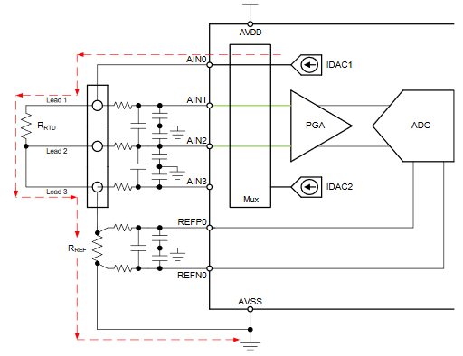
    I have also identified another problem. With a two-wire RTD, the reference resistance is only passed through by the current of one current source.  So I would have to halve the current and double the gain of the three-wire RTD so that the circuit has the same characteristics. For this reason I consider to measure the three-wire with only one current source (see circuit below). But I'm not sure whether the formulas for the cutoff frequencies of the Application Note sbaa201 also apply to this circuit?

    In the case of a two-wire RTD I would conntect Lead2 to the filter input of AIN3 and let AIN2 flooting. This should work?

    Many thanks,

    Cyrill

  • Hi Cyrill,

    There is a problem when you have lots of information and that is the tendency to over think the system. All of the theory has good points to consider, but what you really want is a good result in the end. Matching doesn't necessarily mean an exact value. This isn't really practical or possible. All components have some tolerance associated with the device and not all calculated values are available. The goal is to get close.

    The most important filter is the differential input filter. Common-mode filters are ok to use, but they are not necessary. The discussion in the various application guides talk about the cap value for the common-mode caps (if used) to be 1/10 the value of the differential cap. This is so the common-mode filter has a much higher cutoff frequency compared to the differential filter. The rationale here is to prevent mismatch due to tolerance issues for the R and C values from one input to the other creating a difference voltage in the noise.

    The primary purpose for the input filters on the ADC inputs is for antialiasing. If you have an antialiasing filter on the analog inputs, then to have the lowest noise you want the reference filter to be similar in response to the analog input filters so any residual effects will cancel in the measurement. To show this as an exaggerated effect, the SBAA201 Figure 7 shows the graph of having no input filters on the analog inputs, but having a filter on the reference. As the cap increases, the cutoff frequency lowers and the noise increases in the measurement. You would see a similar effect by switching the filters from the reference to the analog inputs.

    In SBAA330 in the component selection and point 5, there is a discussion about component selection for the filters. In both the analog input filter and the reference filter the design is for a cutoff frequency of 330Hz for the dominant differential filter. The common-mode filters will differ somewhat due to component values, but as I said earlier, these could be completely removed.

    As the differential filter is dominant, let's work things backwards. Let's say we use the same cutoff frequency used in SBAA330 and use 330Hz for the reference filter as well as the same cap value of 47nF. The reference resistor is 2.5k Ohm by your choice. 330 Hz = 1/(2*pi*47nF*(2.5k +2*Rin)). Solving for Rin we have Rin = (1/(330*2*pi*47nF) - 2.5k)/2 = 3880 Ohms. This would not be a standard value so you need to find something close. As you can see it is very difficult to get an exact filter match, but you also do not require large resistances.

    There are many ways to make connections between 2-wire and 3-wires and what you suggest can work. In the 3-wire case the measurement would be between AIN0 and AIN1 and in the 2-wire case the measurement is between AIN0 and AIN3. Note however that the filters are not the same for the differential input for each case. How you deal with the filter depends on whether you use a single IDAC for excitation in the 3-wire case which requires a voltage correction from an AIN2 to AIN3 measurement, or instead you use 2 IDAC sources for the 3-wire connection (not shown in the diagram posted).

    Best regards,
    Bob B
  • Hi Bob,

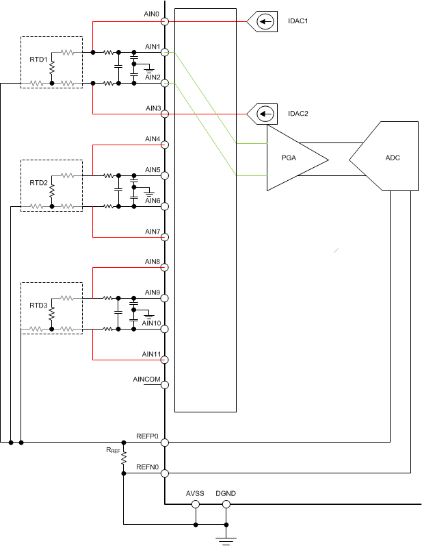
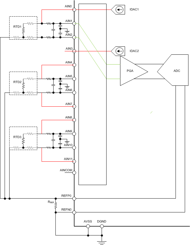
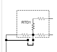
    I now use two IDACs for a 3-wire RTD. So I reduce the current from 1mA to 0.5mA and double the gain to 32. This way the circuit should work exactly the same as with a 2-wire RTD. The circuit can be seen below. In case of a 2-wire RTD I make a connection between the input filter of terminal AIN2 and REFP0 and I deactivate IDAC2 (see RTD1 as an example) .


    The cutoff frequency of the differential voltage is about 230Hz.  So I should have -40dB attenuation at about 20kHz. My sampling rate will be <= 20SPS.


    Input: I choose C_diff=68nF, C_cm=4.7nF, Rin=5.1kOhm

    f_diff = 1/(2*pi*68nF*(2*5100+158)) = 227Hz

    f_cm = 1/(2*pi*4.7nF*(5100+158+2490)) = 4.37kHz

    Output: I choose C_diff=68nF, C_cm=4.7nF, Rin=3.9kOhm

    f_diff = 1/(2*pi*68nF*(2*3900+2490)) = 227.5Hz

    f_cm = 1/(2*pi*4.7nF*(3900+2490)) = 5.3kHz (f_cm2=8.68kHz)


    As filter components I choose resistors with 1% tolerance and ceramic capacitors with 5% tolerance and NP0 dielectric. At the IDAC connectors (AIN0, AIN3, ...) I mount a Schottky diode for protection.

    Kind regards

    Cyrill

  • Hi Cyrill,

    This is the correct concept.  In your system you would need to be able to connect a 2-wire RTD to the 3-wire input.  So in your final schematic you will need to make sure you have a way of connecting so that the 2-wire connects to the reference resistor to complete the circuit for the current flow.  One simple method is to use a jumper.

    Best regards,

    Bob B

  • Hi Bob,

    Yes, of course I forgot to mention that. Thank you very much for your support.

    Kind regards

    Cyrill