This thread has been locked.

If you have a related question, please click the "Ask a related question" button in the top right corner. The newly created question will be automatically linked to this question.

DAC38RF80EVM: LMK Output Clocks

Part Number: DAC38RF80EVM
Other Parts Discussed in Thread: LMK04828, LMX2595

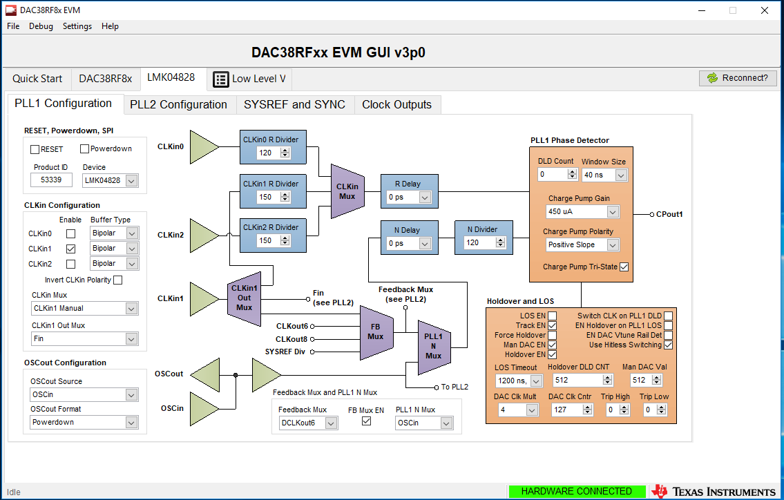
Currently, I am trying to configure the various output clocks at our disposal from the LMK04828 clock synthesizer/jitter cleaner and am having a few issues. I've attached a screen shot of the GUI page where I believe the issue may be occurring: 

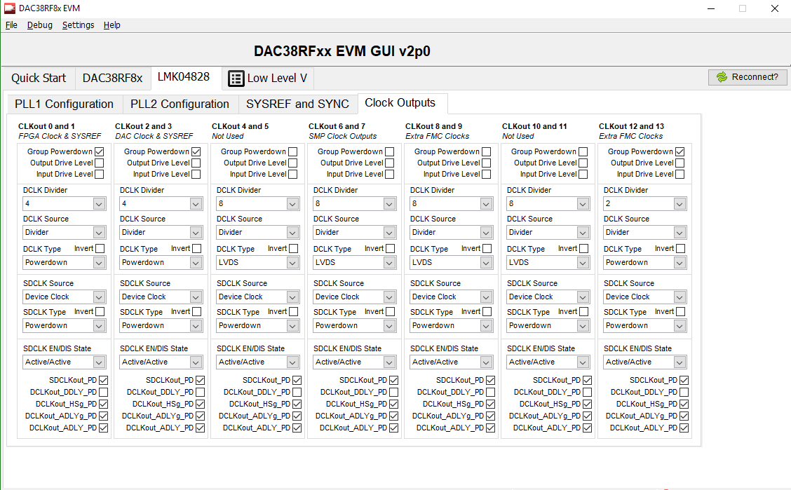
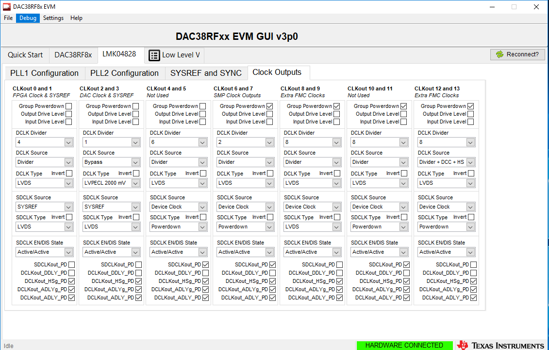
I've been trying initially to produce an output at CLKout 4 since that is connected to SMA J24 just to verify the LMK is working properly before hooking up our FPGA. So far, I have been able to produce an output signal. I've made to sure to uncheck the "group powerdown" checkbox and adjusted the settings seen above. Am I missing something?

I have an input clock at the DACCLK+/- but currently don't have the LMK CLock input at 1/4 of the DACCLK sampling freq. Would that be why, or does something else need changed or some other action have to take place?

Thanks,

Jared

  • Hi Jared,

    We are looking into your question, and will be back with you soon.

    Best Regards,

    Dan

  • Jared,

    I am assuming you have a clock input coming in on J1 to provide the DACCLK+/-. This clock also goes to a clock divider by 4 (U30) that then feeds the LMK. If the shunt is removed from jumper JP10, this divider is powered down and the LMK will not operate. Verify that the shunt is present. Your settings above look fine and there should be an output J24.This will be a low level signal since it is just getting one leg of an LVDS output. 

    Regards,

    Jim

  • Jim,

    Yeah the jumper at J10 was definitely removed for some reason. We are getting an output at J 24 now. Thanks!

    I did notice that the frequency of that signal didn't behave as expected and wonder if you would know why. For instance, I tested it with an input DAC clock freq. of 4915.2 MHz. I know that gets /4 before going into the LMK. Then on the page shown above, you can select to divide the LMK clock frequency by another factor between 1-32. However, two observations have been made:
    1) The frequency J24 doesn't appear to be near the expected output frequency when calculating it mathematically (knowing there would be some tolerance on the value) no matter the the additional division value.
    2) The output frequencies don't appear to be consistent when they are changed. For instance, if I cycle through all the divider values and then return to a previous tried value, I've been getting completely different values.

    Would you have any idea why this would be the case for either observation?
  • Jared,

    Is the LMK configured to operate in clock distribution mode or PLL mode? If it is PLL mode, you probably do not have the VCO locked inside the LMK. If using this mode, the PLL2_LOCK LED should be on, indicating the VCO is locked to the 122.88MHz VCXO. Please send screen shots of all of the LMK tabs if you still need help with this..

    Regards,

    Jim

  • Jim,

    Correct me if I'm wrong, but if an external DAC clock is being used, the LMK should be in clock distribution mode correct? Or do I have to enable the PLL (on the quickstart page), attach a clock to J4 and set it's frequency, and then that's the clock used to synthesize the output clocks from the LMK?
  • Jim,

    Here are the screen shots of the LMK configurations in the DAC EVM GUI along with my clock setup for the LMX2595:

    I believe I have everything set up correctly for clock distribution mode. I configured the DAC to operate with a clock of 4915.2 MHz (default value). So then when it gets divided by 4, I should get an Fin frequency of 1228.8 MHz into the LMK. Then I have DCLKOUT turned on and have the divider set to 6. The frequency I am getting at that SMA however is roughly 350 MHz despite expecting 204.8 MHz. I've tried other divisions, and the math isn't working out for any of them. Am I missing something?

    Jared

  • Jared,

    The LMX clock output should be connected to J1 of the DAC EVM and JP10 should be installed. Based on what I sent you earlier, is there a chance the LMX is not providing enough output power to the DAC interface?

    Regards,

    Jim

  • Jim,

    Based on some testing we conducted here, the output appears to be well within the recommended 3-7 dBm that is called out in the DAC EVM User Guide. 

    Does the LMK IN have to be connected in addition to the DACCLK+/- in order for the FIN signal to be at a high enough power output for clock distribution mode?

    Jared

  • Jared,

    It does not. The LMK is getting its clock from this source after it gets divided by 4. For a sanity check, can you use a signal generator as an input source?

    Regards,

    Jim

  • Jim

    That's what I thought though based off the schematic it looks like the divided clock and LMK input get combined leading into the same LMK FIN/CLK1 input pin.

    I can try using a signal generator. However, due to the board modifications I made to accommodate a differential clock, would the DAC still function properly if I only provide the one input clock signal on the p-leg and program it to be single ended instead? Or will I have to convert the single ended signal to a differential?

    Jared