This thread has been locked.

If you have a related question, please click the "Ask a related question" button in the top right corner. The newly created question will be automatically linked to this question.

ADS54J66EVM: ADS54J66

Part Number: ADS54J66EVM
Other Parts Discussed in Thread: ADS54J66

hi all,

Actually iam using ADS54J66EVM board for testing jesd interface by using KC705 evaluation board.

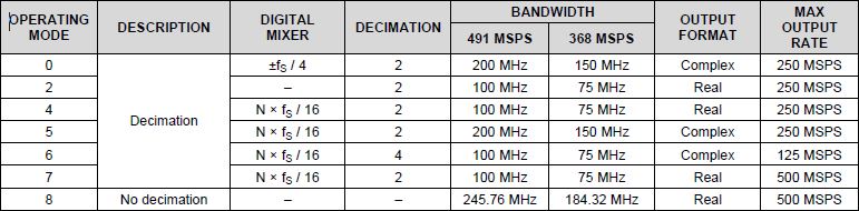
In the ADS54J66 datasheet http://www.ti.com/lit/ds/symlink/ads54j66.pdf  on page no 23, they have given a table for different modes of operation.

I want operate at mode no 8 (no decimation), can anyone explain the relation between input clk frequency to the ADC and output data rate of ADC.

Thank you.

  • Sai,

    With no decimation, the input clock frequency is the same rate as the output data rate. If the decimation was set to 2, the input clock would be 2X the output data rate.

    Regards,

    Jim

  • hi jim,

    can i know the relation between the bandwidth and max output rate section in the table i have mentioned in the above query.

    example : bandwidth 491 MSPS @245.76Mhz is given out as 500 MSPS output data rate.

    thanks

  • Sai,

    The digital filters can only pass roughly 80% of the input bandwidth. So for mode 0, if you are sampling at 500MHz, and decimating by 2, the max data rate will be 250MSPS. The max BW is then 0.8 * 250 = 200MHz.Table 3, figure 54 and figure 55 go into more information regarding this for mode 0. Other tables and figures cover the other modes.

    Regards,

    Jim 

  • hi jim,

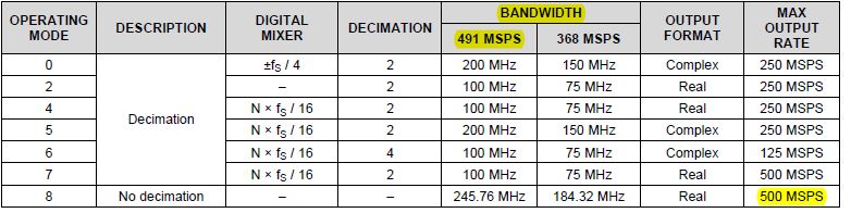
    1.What is relation between 491 MSPS and 500 MSPS which i have highlighted in the below given table?

    2.If i give  a input clock frequency of 491.52Mhz and working in mode 8 then output data rate i'll be getting is 491 MSPS or 500 MSPS?

    thanks.

  • Sai,

    This part was designed for the telecom industry and these are common telecom frequencies (245.76, 491.03, ect...). That is the only reason they are shown. This is the closest to 500MHz.

    Regards,

    Jim