This thread has been locked.

If you have a related question, please click the "Ask a related question" button in the top right corner. The newly created question will be automatically linked to this question.

ADS8688: Input register

Part Number: ADS8688
Other Parts Discussed in Thread: LM35,

Hi, 

My customer uses ADS8688 and LM35DZ (temp sensor). ADS8688 convert analog data from LM35DZ. Temperature slope of LM35  output is 10mV/ degree C from 0mV.

When user connect the output of LM35 to ADC8688, the output of LM35 will not be under 0.1V at low temperature.
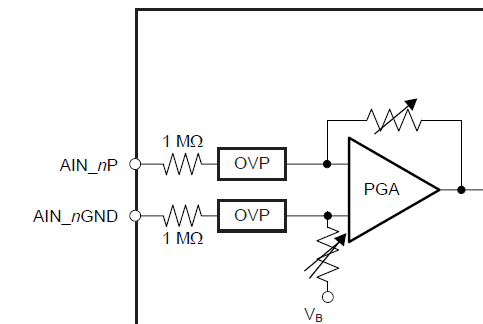
Once he checks LM35 without connection to ADC8688, the output will be close to 0V at low temperature. I believe the output may clamped by ADS8688 input. Because Input of ADS8688 may have internal 1Mohms and OVP. But do you have idea how to release the clamp? 

I'm asking customer schematics but cannot show it in public E2E (this). So, is it possible to discuss this topic with e-mail? could you please let me know contact person? My address is  s-nagata@ti.com.

Regards,
Nagata.

  • Hi Shunsuke,
    Definitely ADS8688 supports direct bipolar or unipolar input signal, I need the schematic to check, and I will send an email to you.
    Based on your information, the minimum LM35's output is 0V, is this correct? It will be great if you can let me know more information: for same temperature test, what are the LM35's output voltage with and without the connection to ADC? What is the digital output code from ADS8688 when it is connected to LM35? Also what is the input range configured by the customer on ADS8688? Thanks.

    Best regards
    Dale
  • Hi Shunsuke,

    I have checked the schematic and I have some concerns:

    1.  The matching input helps to cancel any additional offset error contributed by the external resistance, however, this circuit has a 330ohm resistor on AIN_xP Pin but another 330+250ohm(4*1kohm) on AIN_xGND which is not a matching input. Also, for I-V conversion, generally the resistor should be placed in parallel but these four 1kohm resistors are placed in series with AIN_xGND in this schematic, I do not know how it works.

    2.  Looks like LM35 sensors are not designed on the same circuit board as ADS8688,the ADC's inputs are connected to LM35 with differential connections and remote ground. I'm not sure how long distance from LM35 to ADC board, also the trace distance between the connector (CN5 and CN6) and ADC. Please note that the voltage on AIN_xGND should be kept between -0.3~0.3V which is maximum specification in datasheet. Also, the long trace may pick up noise. Local ground connection is a good solution for ADC.

    These should be root reasons to cause the "issue". I will suggest the flowing tests:

    1.  Remove 4*1kohm resistor and short the connection. Check if the ADC's output is correct.

    2.  Check the distance and trace, try to use local ground for input. Check if the ADC's output is correct.

    3.  If the "issue" still exists, use a precision generator with a DC signal between 0v~0.1V and connect the signal to CN5 or CN6, check if the ADC's output is correct.

    I would like to check the conversion code if the customer can get it.

    ADS8688 has an internal bias voltage (VB: ~2.25v for +/-2.5Vref input range), when there is no input signal (disconnected), the bias voltage will show up, but if there is an available input signal to the ADC, this bias voltage will not appear and the ADC's output will be the conversion of input signal.

    By the way, the customer is using a TVS diode (DY2S15ZC0L) to provide a protection on each ADC's input, but actually the breakdown voltage and stand-off voltage of this TVS diode are too high to protect ADS8688. The DY2S12ZC0L in same family should be a better TVS diode for the protection. Also, a resistor prior to TVS diode and in series with 330ohm should be used to limit the current for transient signal clamping. A Precision Labs training/video series about ADC input protection will be available on TI.com in April.

    Please let me know these experiments result, thanks.

    Best regards

    Dale

  • Hi, Dale -san,

    Thank you for your support. As I comfirmed with customer, I misunderstood his schematic. Could you please confirm the latest one which I send to you?

    The resistor (4*1 kohms) are not connetct to GND line. And customer checked that conversion data from ADS8688 using with DC signal between 0~0.1V instead of LM35. In this case, he confirmed the conversion data is converted as expected. Customer would like to know the circuit consists RC-filter (330ohm + 0.01uF) and input of ADC ( 1Mohms + OVP + adjustable feedback register of PGA as below ) may cause this phenomenon. So, could you please give your advice for this requirement?

    Regards,
    Nagata.

  • Hi Nagata-san,

    Can you explain what you mean about "The resistor (4*1 kohms) are not connected to GND line."? In the block diagram, you showed that these resistors are connected to the LM35's output which is connected to the ground as well.

    Based on the customer's latest experiment, the conversion code of ADC was expected when the input was DC signal between 0~0.1V instead of LM35, so there is no issue for ADS8688, also there is no any issue with the front-end RC(330ohm+0.01uF). This is a common RC filter on EVM board. The issue should be caused by LM35 or the connection to LM35.

    I'm looking forward to seeing your answer for my question.

    Thanks&regards

    Dale

  • Hi, Dale -san,

    I send the latest circuit. There are 330ohm register in AIN_n line and AIN_nGND line. The absolute maximum output current is 10mA. Is there relation between this output current and RC filter + impeadance of input of ADS8688 for this phenomenon.

    Regards,
    Nagata.
  • Hi, Dale -san,

    Could you please give me your advice for this?

    Regards,
    Nagata.

  • Hi Nagata-san,

    I apologized for late response, my laptop stopped working on Friday and had to re-install Windows 10.

    Definitely there is a relationship between LM35 and the circuit. Can you please remove TVS to check? Also, can you please let me know which version LM35 the customer is using? thanks.

    Best regards,

    Dale

  • Hi, Dale -san,

    Thank you for your support. I will check if the state would change without TVS. But why do you need the revison of LM35? As I check the revision history in datasheet, I could not find specific item to care for this. Unfortunately I have no idea how to get the revison from LM35 customer use. So, could you please let me know which charactoristics are required in LM35? I will ask them to LM35 BU team.

    Regards,
    Nagata.

  • Hi Nagata.

    There are LM35,LM35A, LM35CA,LM35C and LM35D,they have different specifications. I want to know which is right part you are using and I want to check the detail about the device. Thanks.

    Regards,

    Dale

  • Update: communicated with Nagata offline because of LM35 from different team, the issue has been identified, the reason why the customer could not get conversion result less than 0.1V is, LM35 has one large output impedance(R2+0.125R2) on the output, it created a offset voltage with 1Mohm input impedance on ADS8688 when LM35 is connected to ADC's input. The query will be closed because it has been identified. Thanks.