This thread has been locked.

If you have a related question, please click the "Ask a related question" button in the top right corner. The newly created question will be automatically linked to this question.

ADS1120: Problem with compression near FS in negative measures.

Part Number: ADS1120

I use the ADS1120 to realize measures between ±20mA.
The equipment has 8 cells with one ADS per cell. This cells are isolated between itself.

In many of this cells the funcionality is Ok, the componente work well.

But in the last production i see 6 componentes that have a compression mistake in negative measures, only, and near FS.

One of the test is a curve for test the lineality of input. I put in the inputs, values between -20 and 20mA with 1mA of step.

The table of results is:

Input CH1 Dif-esl CH2 Dif-esl
0 0 -1
1 -818 818 -818 817
2 -1637 819 -1636 818
3 -2456 819 -2454 818
4 -3274 818 -3273 819
5 -4093 819 -4090 817
6 -4911 818 -4908 818
7 -5730 819 -5727 819
8 -6549 819 -6545 818
9 -7368 819 -7363 818
10 -8185 817 -8182 819
11 -9004 819 -8999 817
12 -9823 819 -9817 818
13 -10641 818 -10636 819
14 -11460 819 -11454 818
15 -12587 1127 -12577 1123
16 -13434 847 -13427 850
17 -14205 771 -14200 773
18 -14998 793 -14992 792
19 -15747 749 -15739 747
20 0 -15747 0 -15739
0 0 -1
1 819 819 819 820
2 1637 818 1637 818
3 2457 820 2455 818
4 3275 818 3274 819
5 4093 818 4091 817
6 4911 818 4910 819
7 5730 819 5727 817
8 6548 818 6545 818
9 7367 819 7363 818
10 8185 818 8181 818
11 9004 819 8999 818
12 9823 819 9818 819
13 10641 818 10636 818
14 11459 818 11453 817
15 12279 820 12272 819
16 13097 818 13090 818
17 13915 818 13908 818
18 14733 818 14726 818
19 15553 820 15544 818
20 16371 818 16363

819

Dif-Esl this tbale is de differencie between one step and the next step.

If the lineality is ok, all steps would be identical and the part positive and negative would be like each other.

This measure is of one of this cells, in the other cells the measure is ok, and the side positive and negative are identical.

My question is about if this problem has seen any time? Or if this is a problem with these ADC's. 


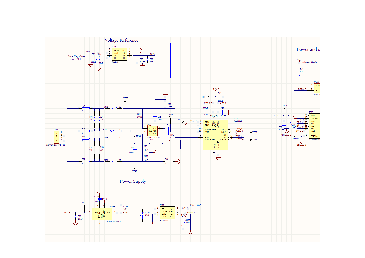
The circuit of cell, if you want, i can send you.

  • Hi David,

    Yes it would be helpful to see the schematic and also to know the register settings being used. The linearity is shown in the datasheet in the electrical characteristics table on page 7. Typical INL is 8ppm of the full-scale range (FSR) and worst case of 20ppm. The linearity is also shown graphically in Figures 7 through 10.

    Depending on your FSR you may see some variation but not the degree of variation you are showing. As I do not know the reference voltage, gain settings or specific information regarding your setup I cannot give a precise value.

    The only time I have seen an issue with linearity is when the input voltage not within the correct common-mode input range, or if large series resistors are used for input filtering.

    Best regards,
    Bob B
  • Ok. I add the cell of on analog input. 

    The registers settings are following:

    Initial Config:

    4000 (0100 0000  0000 0000)

    44D0 (0100 0100  1101 0000)

    4850 (0100 1000  0101 0000)

    4C00 (0100 1100  0000 0000)

    first capture

    4000 (0100 0000  0000 0000)

    0008 (0000 0000  0000 0100)

    0000 (0000 0000  0000 0000)

    4050 (0100 0000  0101 0000)

    0008 (0000 0000  0000 0100)

    The supply voltage is 2.7V and the external reference is 2.5.
    The input is 20mA, that in the ADC input is 2.5 volts.

    The serial resistors are 1k, is it possible that are large?
    Is it preferible 100?

  • Hi David,

    I didn't get the picture/drawing you attached.  Make sure you follow the following directions when attempting to insert pictures or files:

    Reviewing your registers settings you have set the device to Turbo mode so that the data rate is running at 2000sps.  You are using PGA enabled at a gain of 1, which restricts the common-mode input range as given in section 8.3.2.1 of the ADS1120 datasheet on page 22.  You have also set the digital filter to simultaneous 50/60 Hz rejection which only works in normal mode at 20sps or duty cycle mode at 5sps.  So when operating in turbo mode this setting is ignored.

    With the ADS1120 powered by 2.7V, with PGA enabled and using a gain of 1,  the common-mode input range becomes 0.675V < AIN < 2.5V.  It is not clear how you are connecting the inputs to the shunt for the current to be measured.  1k series resistance is fine to use, but the actual input voltage relative to AVSS and AVDD are very important as this input voltage must be within the common-mode input range defined above for a 2.7V unipolar analog supply.

    As the measurement is showing a relative input voltage from 1.25V to -1.25V means that the AINP input moves about a voltage that has a range of 2.5V.  Normally you would have a fixed voltage for AINN that would allow this measurement range.  If the input for AINN is connected to 1.25V, you can input a voltage to AINP that can range from 2.5V to 0V.  As the measurement is relative to the voltage at AINN, an input voltage at AINP of 2.5V gives an output code value of 1.25V and if AINP is 0V, the the output code voltage value is -1.25V.  However this input range is only valid when the PGA is disabled and bypassed.  With the PGA enabled you are restricted to an input voltage at AINP of 0.675V to 2.5V, otherwise you would be in the non-linear range of the PGA.

    If your system is connected similar to as how I've just described, you should disable the PGA to allow the full measurement range desired.

    Best regards,

    Bob B

  • Hi Bob.

    Yes, the analog input is conected for that FS are 2.5V os -2.5V. with a resistor to change the current (20mA) to voltage(2.5V).

    Ok. I change and disable PGA for this design. And I'll testing de equipment.

    But if i need add a gain with ADC. is it better change the operating mode and put a normal mode?

    Thank you.

    David.

  • Hi David,

    Could you try attaching again by using the paper clip icon (to attach a file)?  The insert media icon is looking for a picture file like .png, or .jpg. files. Unfortunately you can not drag/drop or copy/paste pictures or other files and must click on the appropriate icons to insert pictures or files.

    Operating with PGA disabled you can achieve gains of 1, 2 or 4.  If you need gains greater than 4 you will need to have the PGA enabled and make sure the input voltage is within the correct common-mode range.

    There is no difference in the operation between the normal mode and turbo mode with respect to the operation of the PGA.

    Best regards,

    Bob B

  • Hi Bob.

    I were trying up load a PDF file. Sorry.


    Ok. I change the PGA parameter.

    Thank you.

    David.

  • Hi Bob.

    The change is OK.

    Thank you.