This thread has been locked.

If you have a related question, please click the "Ask a related question" button in the top right corner. The newly created question will be automatically linked to this question.

ADS1115: Can I use a differential input and 2 single ended inputs at the same time?

Part Number: ADS1115

Hi,

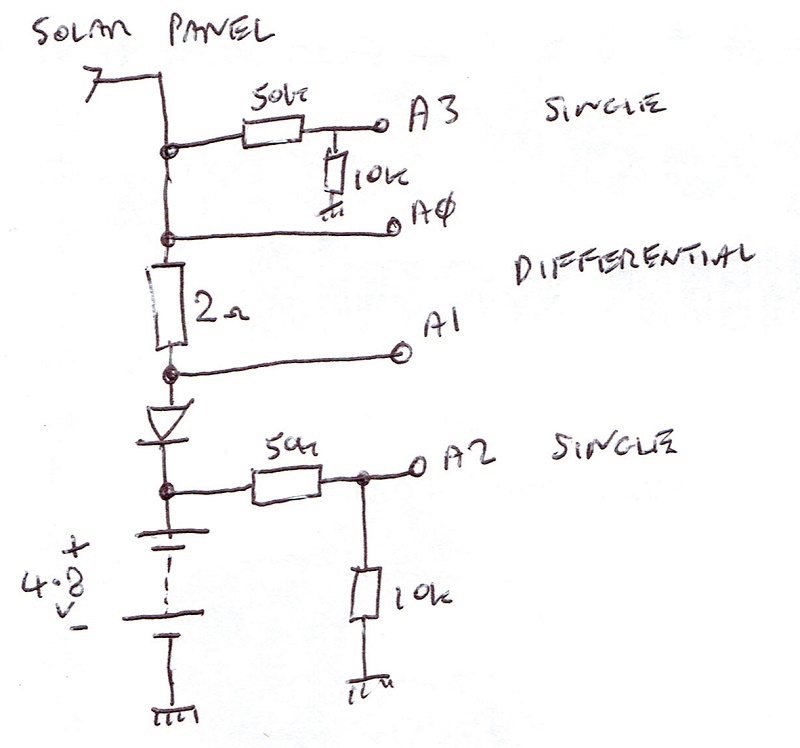
Is it possible to operate A0 and A1 in differential mode whilst A2 and A3 are in single ended mode referenced to ground?

I have only seen reference to using differential or single but not both at the same time.

Is it possible please?

Just for more clarity of my reason...

I wish to measure the voltage drop across a resistor to calculate current flow and  record a battery voltage on one single ended input and solar panel voltage with another single ended input referenced to ground.

Thanks

Martin

  • Martin,


    Just to be sure, can you post a simplified schematic?

    In short, yes, you can operate A0 and A1 as differential measurements, while measuring A2 to ground and A3 to ground as single ended measurements. The input is just a basic multiplexer that can be configured for each. However, there are two things to keep in mind.

    First, I think it's best to use the single shot conversion mode when making a series of different measurements. It eliminates the questions about when the multiplexer changes, and when the conversion starts.

    Second, single ended measurements are basically differential measurements with one end grounded. Because of this, the output data for a differential measurement is a 15 bit result, basically only positive outputs (note there might be a small negative output with a small offset error).


    Joseph Wu

  • Hi Joseph,

    Thank you for your reply.

    I hope I have attached a 'simplified' schematic.

    One thing I have now noticed after giving it a try is that the differentail is comming out at 0 regardless of the input.

    I suspect that the differential should maybe be wrt ground. In other words, maybe it measures A0 wrt gnd and A1 wrt gnd then takes one from the other to give a differential value.

    Unfortunatly my inputs are not reference to gnd which maybe why they are reading 0.

    Could this be the case or is there something wrong?

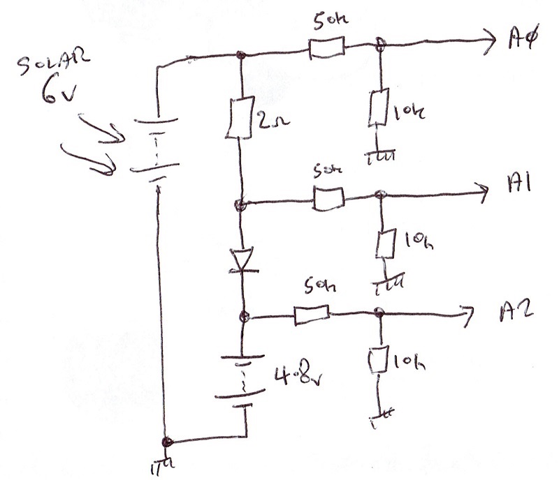
    Also, there are floating voltages on the single ended inputs of around 1 volt. These are effecting the readings. I suspect maybe my potential divider on the inputs is using too higher value resistors (52k/10k) for a 6:1 reduction. Do you think I should use smaller values, maybe 5k/1k?

    Thanks

    Martin

  • Hi,

    I have a second idea and question.

    If I use only 3 inputs can I take a differentail reading between A0 and A1, then take a further single ended reading on A0, then another on A2.

    In other words, can I do both?

    That way I will have a spare input (A3) for future use.

    I am aware that I could just take single ended inputs and use software to take one value from the other, but in that case what would be the point of having differential inputs.

    Thanks

    Martin

  • Martin,


    In the last two posts, there were quite a few comments, so let me address them.

    First, differential measurements are not measured with respect to ground. If the inputs are in the input range of the ADC, then the ADC should be able to make the differential measurement.

    Second, I'm not sure of the voltage of the power supply you're using, however, regardless of the range setting of the ADC you should not exceed the supply voltage. For example, if you're using 5V supply, the analog input pin should not be at 6V. I mention this because in you're first post of the schematic, A0 and A1 may be high voltage.

    Looking at the second schematic, you should be able to make a differential measurement with A0 and A1, and then make single ended measurements with each of the other inputs. You would still have A3 leftover to make another measurement. Each of these inputs would be much smaller than the 6V, so you won't have problems with the inputs going beyond the supply.

    However, there are two things to consider. First, make sure that the measurement ground and ADC ground are shared. The ADC isn't designed to make floating measurement, and the should share a common DC ground point. Second, the series resistance of 50kΩ is rather high. If possible, I would lower this resistor divider. The input sampling looks like an equivalent input impedance, which will give you some error as you put the input impedance in parallel with the 10k resistor. The input impedance is a bit complicated, with both a differential and common-mode impedance contribution. There's more detail on page 16 of the datasheet, but there are some impedance values from the electrical characteristics table:


    Joseph Wu

  • Hi Joseph,

    Thank you for the information.
    I am using the ASD1115 in default 2/3rds FSR so the input impedance is very high 10 to 22 Mohm. Using a 10kohm resistor to ground across the inputs should not effect them but I am still getting floating voltages from them.
    For example, my solar panels are at 0 volts, but I have an indications on 0.2 volts, this is due to a floating voltage on the input. I thought maybe I should use a lower value.

    I have since built the circuit now, tested it and it is up and running. Everythng seems good at the moment.
    Thanks
    Martin