Because of the holidays, TI E2E™ design support forum responses will be delayed from Dec. 25 through Jan. 2. Thank you for your patience.

This thread has been locked.

If you have a related question, please click the "Ask a related question" button in the top right corner. The newly created question will be automatically linked to this question.

Instruction for testing a TSW1400 EVM with an ADS5484 EVM

Other Parts Discussed in Thread: ADS5484EVM, ADS5281EVM, ADS5484

Hello,

I have another problem when running the HSDC Pro to capture date from ADS5484EVM using TSW1400EVM. When I run capture data, I always get an error as below. I use external sources for both ADC clock (15 MHz) and ADC input (1 MHz). All USER_LEDs on the TSW1400 are on, except USER_LED4 and USER_LED5. I run HSDC Pro version 5.0 on PC windows 10 64 bits

Could anyone tell me what the problem is? If I just want to capture data from ADS5484EVM only, do I need to use any of SMA ports ((such as SYNC1-4, EXT_TRG_INPUT, and CMOS_CLK) on the TSW1400? What are they used for?

Sincerely.

  • Hi Thinh,

    We are looking at your question and will get back to you soon.

    Regards,
    Neeraj
  • Thanks Neeraj. Since I need to get the hardware worked for a demo by this Thursday, please help me solve this problem as soon as possible. I'm look forward to hearing from you.
    Regards,
    Thinh
  • Hi Neeraj,

    Have you had any update for my issue?
    When I tried several firmwares located in folder C:\Program Files (x86)\Texas Instruments\High Speed Data Converter Pro\1400 Details\Firmware, I did get the HSDC Pro run but the result from Real FFT was not as I expected. The SINAD is too low and thus the ENOB is too small (please look at the below picture). I don't know if I selected the correct firmware. Could you please tell me what is the correct firmware for this combo?


    Regards,
    Thinh

  • Hi Thinh,

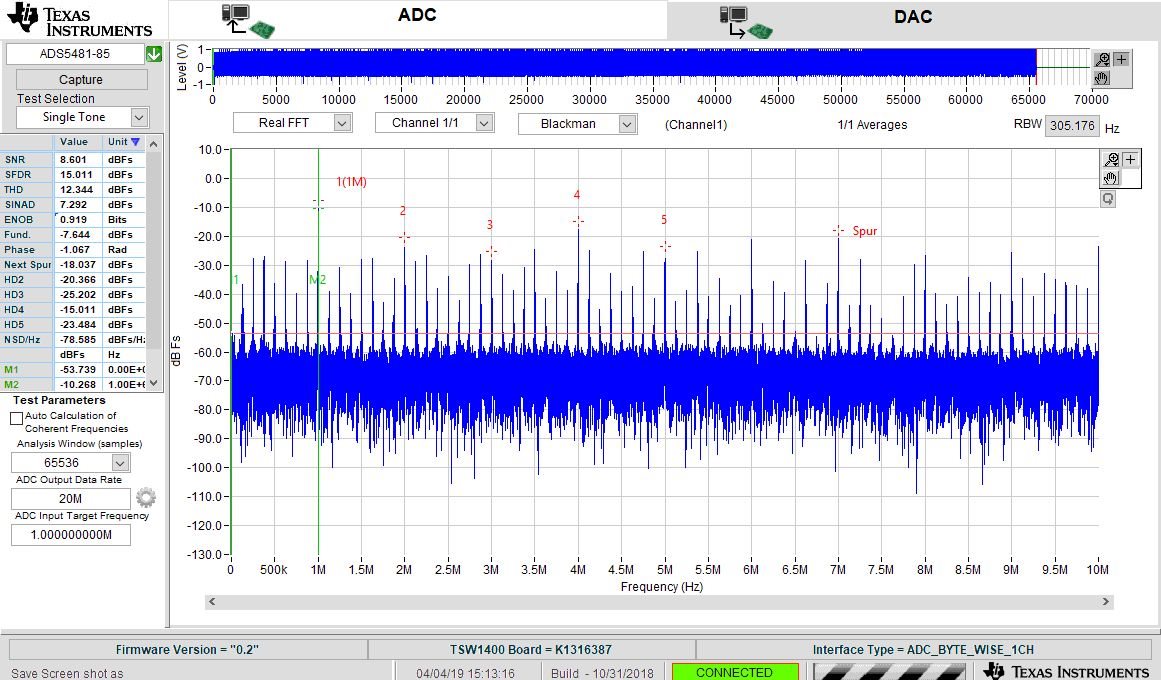
    I am seeing the same issue that you have shared. Are you able to provide a higher frequency clock input? Have you tried varying the clock amplitude?

    Althought the datasheet specs that the minimum clock frequency is 10 MSPS, I think that this might be pushing the performance, at least on this EVM. I have been able to get better performance at MSPS. This capture was using the ADS5481EVM and TSW1400EVM.

    Best Regards,

    Dan

  • Hi Dan,

    I really appreciate your sharing. It's so helpful to me.

    I used function generators, which can provide max frequency of 20 MHz, for both the sampling rate and the input signal. I varied the input amplitude from 1-3 Vpp and frequency from 100 KHz - 1 MHz, but I hadn't tried to vary the clock amplitude yet. I followed the the test suggestion in the TSW1400EVM User Guide (TSW140x High Speed Data Capture-Pattern Generator Card, page 12-15), but I used 20 MHz clock for ADS5484EVM instead of 40 MHz for ADS5281EVM . Also, I run HSDC Pro 5.0 on Windows 10 64-bit.

    I'm thinking about some reasons as below but I'm not sure what is the case.
    1. Can the HSDC Pro software run correctly on Windows 10?
    2. Does the sampling rate affect the SINAD (and ENOB)?
    3. The ADS5484 has an internal reference voltage of 1.2 V, what does this reference voltage really mean? Do I have to set the offset of the input amplitude to this value?
    4. What is the correct firmware for TSW1400EVM to work with ADS5484EVM? I tried several firmwares such as ADC_FIRMWARE, ADC_FIRMWARE_FCLK_ADJUST, ADC_BYTE_WISE_1CH, and ADC_1W_16b but none of them worked.

    Could you please share a little more detail about the set up of your test? Did you use sine or square wave for the clock and the input signal? Did you set any offset for the amplitude of the input signal?

    Thank you for your time.

    Best regards,
    Thinh
  • Hi Thinh,

    Please let me know if increasing the clock amplitude has any effect on your data capture.

    1. We have not had any reported issues using HSDC Pro with Windows 10.
    2. The datasheet is not explicit with this information, and can only guarantee performance that is clearly stated in datasheet. As speculation, I would say that the performance will decrease (some) as you approach the minimum supported sampling rate.
    3. No, you do not need to incorporate an offset. This is already done with the VCM (3.1VDC) being coupled to the analog input. The 1.2V reference is generated internally.
    4. The correct firmware (ADC_BYTE_WISE_1CH) is loaded when you select ADS5481-85.

    For the clock, I used a sine wave input from an SMA100, and I varied the amplitude from +10 dBm to +20 dBm. I also tried with a bandpass filter, but this isn't necessary for functionality. I also used an SMA100 for the analog input.

    Best Regards,

    Dan
  • Hi Dan,

    Thank you for your sharing. I will definitely update the result when I get it done.
    Also, I see a SMA port named CMOS_CLK (J7) on the TSW1400EVM, but I don't know what it is used for. I just wonder if I can take this clock to provide the sampling clock to ADS5484EVM because I don't have any high frequency function generator available now.

    Best regards,
    Thinh

  • Hi Thinh,

    The CMOS_CLK (J7) on the TSW1400EVM is used for devices connected to the CMOS_INTERFACE (J1). Some CMOS evaluation modules require a clock input via the TSW1400EVM, and this is how we achieve that. In this case, J7 will not be helpful.

    Best Regards,

    Dan

  • Hi Dan,

    Is there any way for the ADS5484EVM to get the clock from the TSW1400EVM?

    Thanks for your confirmation.  I really appreciate it.


    Best regards,
    Thinh

  • Hi Dan,

    How are you doing? I would like to update some info regarding my case.

    1.  with 20 MHz clock source, varying the amplitude does not improve the performance. I was still not able to capture data I need. The ENOB is always less than 1 bit.

    2.  with 200 MHz clock source, the ENOB is much better, up to 9 bits depending on the input frequency.

    However, I had some other issues.

    1.  Every time I changed the input frequency, the HSDC Pro did not update the result (after updating the new value in "ADC Input Target Frequency" and clicking "Capture"). In order to capture new data, I had to re-download firmware or turn off and on the hardware but this troubleshooting was not always successful. The probability of success was only 30% or less.

    2.  When data was captured, every time I clicked on "Capture" button, the ENOB kept decreasing.

    I used sine waves for both clock source and input signal. I just wonder if the ADS5484EVM can work with clock source (200 MHz) that is higher than its maximum sampling rate (170 MSPS). I also doubt if there is anything wrong with the hardware.

    Any help or suggestion would be greatly appreciated!

    Best regards,

    Thinh

  • Hi Thinh,

    Have you had further success with the evaluation? I have not been able to make substantial progress on my side, and, due to limited bandwidth on my end, will need to close this thread. Unfortunately, this EVM is quite old, and the original EVM designers are no longer available as a resource. If I am able to find a solution, I will repost here.

    Best Regards,

    Dan
  • Hi Dan,

    Unfortunately, I have not had any further success with it yet. My project was due already without any good results from the TSW1400EVM. I think TI should not sell any product to its future customers without providing a good support, especially with old EVM. TI should not sell its outdated products and leave its customer struggling with them.

    Thank your for time. I really appreciate it.

    Regards,
    Thinh