This thread has been locked.

If you have a related question, please click the "Ask a related question" button in the top right corner. The newly created question will be automatically linked to this question.

ADS1262: ADS1262 Load Cell Schematic Review

Part Number: ADS1262

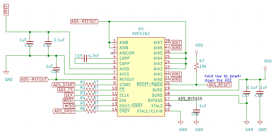
Any chance someone could review this schematic. I'm pretty new to circuit design (I'm mostly a software guy). VREF is 5vdc from a UA78M05CDCYR.

I'm not worried about getting this 100% correct. I just want to get as-good or better readings than a HX-711. I guess I'm just looking to make sure I didn't completely screw something up so at the end of the day I can at least write code for it and get some reasonable load readings. I can revisit this for high accuracy once I prove out the basic concept.

  • Hi spanky,

    I looked over your schematic and didn't find any issues.

    My only recommendation is take care during layout to make sure decoupling capacitors are close to the IC and, if you can, dedicate an entire PCB layer to ground to provide a low impedance path to ground.
  • Thanks. so the 5v coming in on VREF from the UA78M05CDCYR is good enough (and correct)? Also the unattached AINCOM?

    And then I power the loadcell off the same 5v/VREF, not REFOUT, correct?

    I've been trying to follow the spec sheet. I'm just a bit clueless on this sort of thing.
  • Hi spanky,

    To make your load cell measurement ratiometric (immune to changes in the bridge excitation voltage), I recommend that you use the same 5V excitation voltage for the ADC's reference voltage. The ADS1262 allows for an external 5V reference input on the AIN0/AIN1 pins, so your good there!

    I wouldn't recommend powering the load cell off of the 2.5V internal reference for two reasons: 1) The internal reference can only drive about 10 mA of current and 2) You'll get a larger differential voltage output from your bridge by using the larger 5V excitation source.