This thread has been locked.

If you have a related question, please click the "Ask a related question" button in the top right corner. The newly created question will be automatically linked to this question.

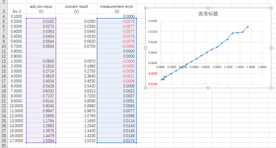
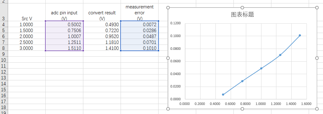
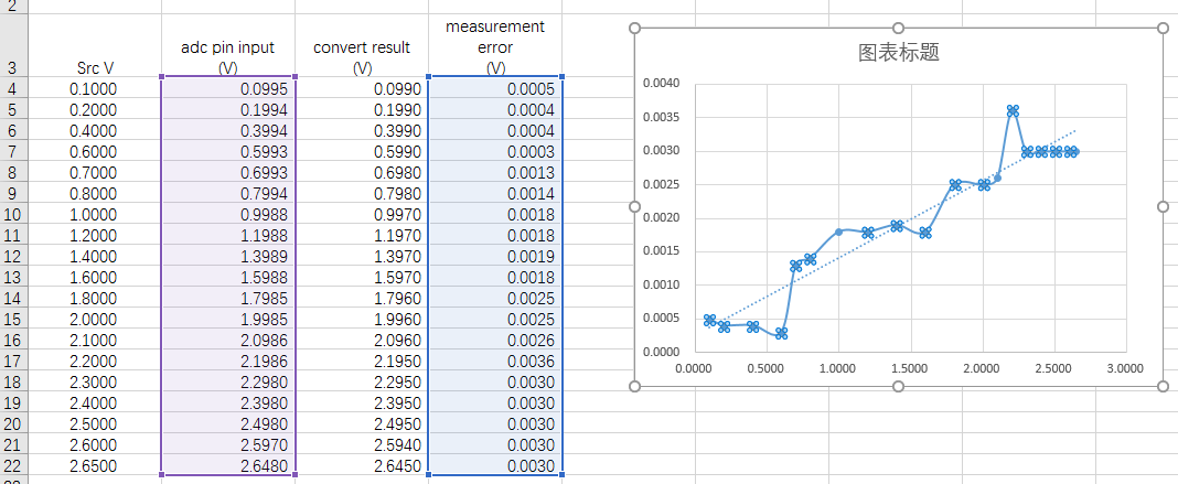
ADS1258: Measurement error is too large, Unacceptable

Part Number: ADS1258

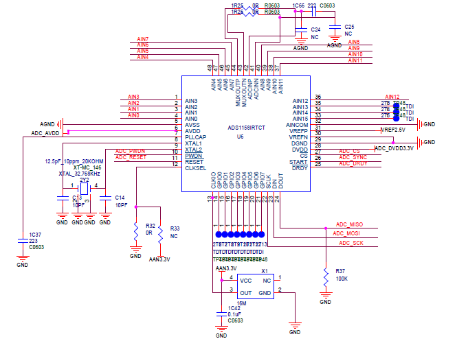
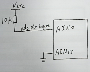
The sch is below.


Test enviromnet:

1. Crystal select: 32.768 kHz

2. AVDD: +5V,   AVSS: 0V,  VREFP: +2.5V,    VREFN: 0V

3. Work mode: fix mode,

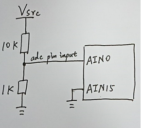
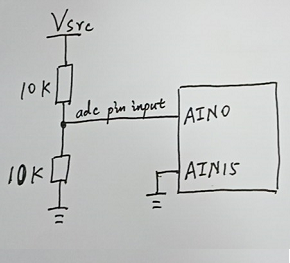
4. Channel select: P: AIN0 (adc sample input), N: AIN15(connect to GND)

5. Registe confog:


Test Case:

case 1: 10K/1K


case 2: 10K/10K


case 3: 10K/∞

6266.Test_Ads1258.doc

Test_Ads1258.xlsx

  • Hi Jashon,

    Welcome to the TI E2E Forums and thanks for sharing  your schematic!

    There are many different reasons why an ADC conversion result may not match what you expect. I see a couple of improvements that you can make to your circuit which should help to reduce the measurement error you are observing...

    1. The analog ground (AVSS) and digital ground (DGND) of the ADS1258 need to be connected to the same ground plane (in the case of a unipolar 5V analog supply, such as you are using), and ideally they should be shorted at the IC. If these ground pins have a difference in voltage potential you could see unexpected conversion results, the device may become unresponsive, or you could possibly damage the device. I usually recommend using a single ground plane with our Precision ADCs (see: [FAQ] PCB Layout Guidelines and Grounding Recommendations for High-Resolution ADCs).
       
    2. The inputs to the ADS1258 go directly into an unbuffered delta-sigma modulator (a switched-capacitor circuit), which does not have very high input impedance. The input impedance will combine with the output impedance of your source (in this case, the equivalent impedance of the voltage divider) to form an additional voltage divider. Hence you will see a non-linear gain error, since the input impedance of the ADS1258 will likely change as you change the input voltage amplitude. I would recommend buffering your input signal, similar to the example given in Figure 67 of the ADS1258 Datasheet.

    3. Any errors in the reference voltage source will translate to errors in the ADC conversion result. Make sure your reference source is buffered. Also, it is recommended to add a differential filter capacitor between VREFP and VREFN to help stabilize and reduce the voltage reference noise.

    4. Add decoupling capacitors to the ADC's supply pins. There should be some decoupling capacitors between DVDD/DGND as well as AVDD/AVSS to stabilize the supply voltages and help filter any noise on the supplies.

    5. Add a 47-Ohm series resistor to the SCLK pin. Clocks often have very fast digital signal edges that interfere with nearby signals due to capacitive coupling. To help reduce this type of interference and also help with signal integrity, I would recommend adding a series resistor on the trace that connects to the ADC's SCLK pin to slow down very fast digital edges. This resistance will form a small RC filter with the parasitic input capacitance on the SCLK pin which can be utilized to create a small filter.

    I hope that helps!