This thread has been locked.

If you have a related question, please click the "Ask a related question" button in the top right corner. The newly created question will be automatically linked to this question.

ADS1220: reset problem

Part Number: ADS1220
Hello,
I am using Python code running on a Raspberry Pi to query the ADS1220 for data with a SPI clock rate of 10kHz.
I am using the DRDY pin and have configured the ADS1220 part for 20 SPS. Below are the settings I am using for the part's 4 registers.
Reg 0x00 = 0x01
Reg 0x01 = 0x04
Reg 0x02 = 0x42
Reg 0x03 = 0x60
My code reads these register values back and confirms they have been properly set.
These register settings configure the part as follows...
20 SPS
unity gain, PGA is disabled
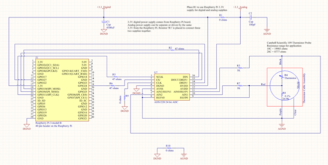
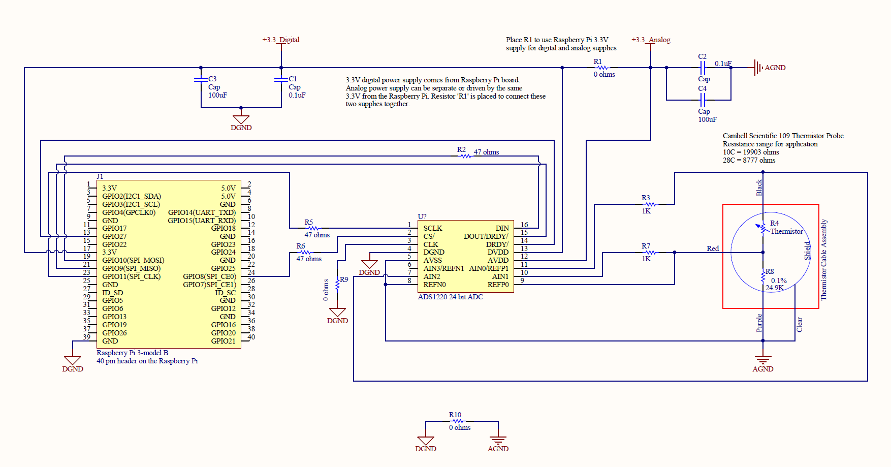
external reference selected using REFP0 and REFN0
AINp = AIN0, AINn = AIN1
IDAC2 is disabled
IDAC1 is enabled and set to 50uA and connected to AIN2
No 50 or 60Hz rejection filters are applied
Temperature sensor is disabled
Burn our current source is off
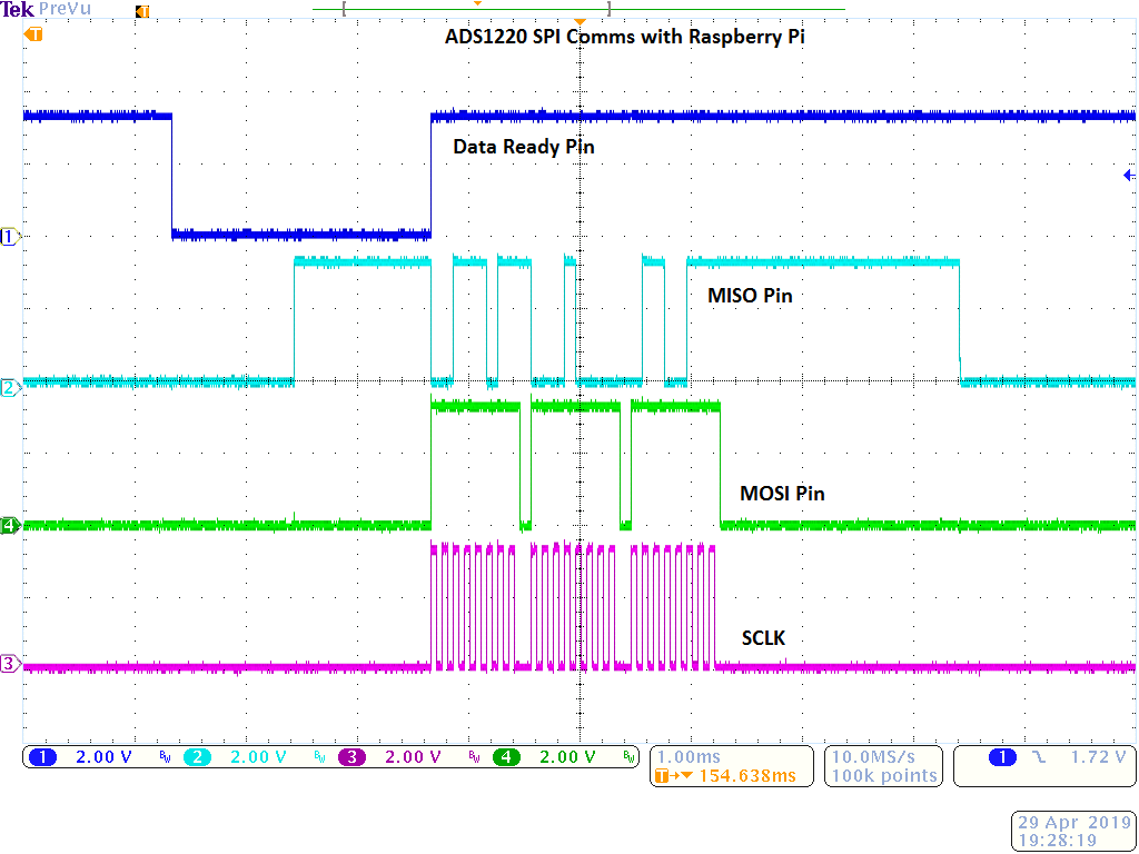
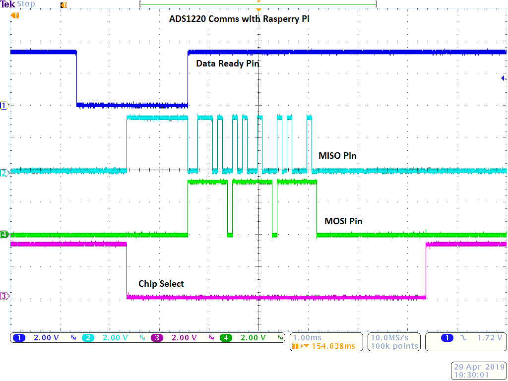
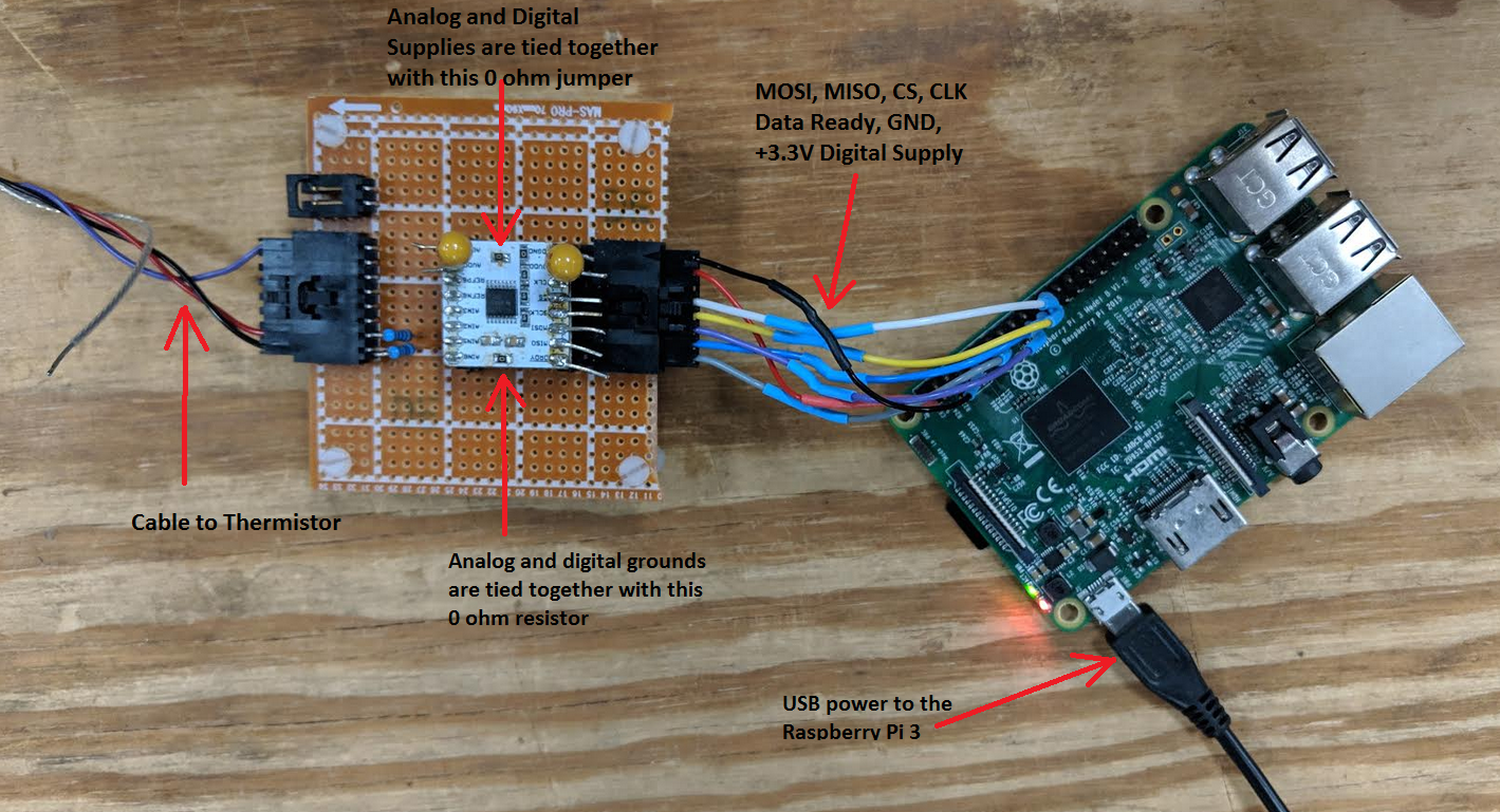
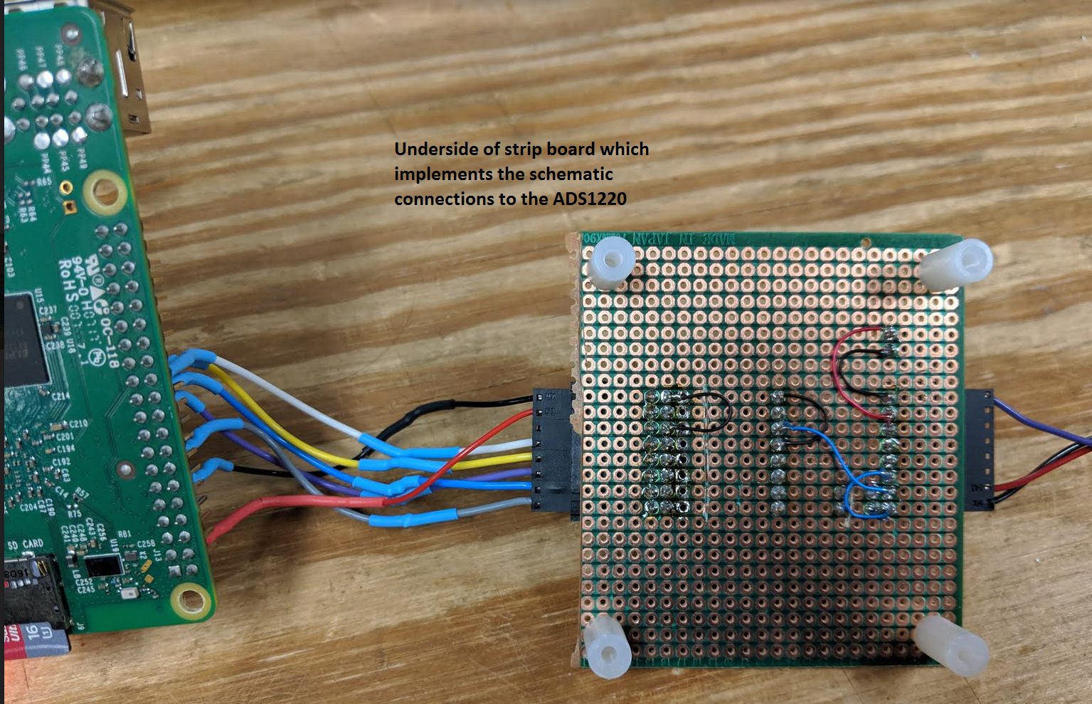
I am then able to query the part for data successfully and the data is valid. I see 20 SPS as expected. My system triggers off of the data ready line going low which initiates SPI comms to clock each sample out of the part. This is working well. However I have noticed that after several minutes or so of continuous data collection the part somehow resets and the 4 configuration registers return to their default value of 0x00. This of course stops the part from continuously sampling. I can then restart my code and everything works just fine... but after several minutes or so the problem repeats. This behavior is very repeatable. The part's digital and analog supplies are tied to an external 3.3V supply that is good and solid. The digital and analog grounds are connected together as well. The Raspberry Pi and external 3.3V supply share the same ground. The SPI comms look very clean and free of noise when viewed on an O-scope.
So I am confused as to what could be causing this behavior and appreciate and suggestions you may have.
Thank you.

-Sean 

  • Hi Sean,

    This sounds like a transient event is taking place that may be caused by ESD (physical touch with a charged body for example), EMI (from a nearby motor as an example) or RFI (from a cell phone as an example). This could be happening on the supply or coming in on the analog/digital inputs. Anywhere that you have a 'wire' interconnect is a possible source for the issue as the wire will act as an antenna. Make sure your interconnecting wires are as short as possible and do not cross over other wires.

    I would suggest limiting the potential sources to as few as possible to try and determine what may be causing the issue. I would start by disconnecting the analog and verifying that the issue is not from the supplies or the digital signal lines. If this appears to be working, then I would suggest reconnecting the analog piece by piece.

    Best regards,
    Bob B
  • Hi Bob,

    Thank you for the suggestions. I will reduce the length of the digital SPI comms as well as the Data Read pin between the Raspberry Pi and the ADS1220 evaluation board. Currently they are roughly 8" in length and I will reduce them to as short as possible which will probably be around 2" or maybe less. I understand what you are saying regarding ESD, EMI or RFI as possible causes. For my application there are no motors involved, only a thermistor. All the failure instances have occurred when there was no physical contact with any part of the system on the bench in the lab.

    I will also disconnect the analog and run the digital SPI comms to see if the issue repeats itself as you suggested.

    Thank you for the help and recommendations. I will let you know how how the trouble shooting goes.

    -Sean
  • Hi Bob,

    I greatly reduced the SPI bus length on my setup but unfortunately this did not resolve the reset issue.

    I also attempted to test the system with no analog power connected and only digital power applied. However the ADS1220 is non responsive to SPI comms when no analog power is applied and only digital power is applied. Is this expected?

    So I must have both digital and analog power supplies connected in order to have valid SPI comms with the part. I have also noticed that if I separate the analog and digital power grounds then the sample rate drops to 5 SPS. As soon as I connect digital and analog grounds together the part returns to the 20 SPS rate. This behavior confuses me. Its as if somehow the part is dropping into Duty Cycle mode when the analog and digital grounds are disconnected.

    Thank you
    -Sean
  • Hi Sean,

    Perhaps I was not clear. When I meant to disconnect the analog components, I meant to disconnect anything connected to the analog inputs. Both the analog and digital supplies must be at the nominal operating voltage or the ADS1220 will be held in a reset state. You cannot communicate to the device while it is in the reset state.

    When you say that you 'separate the analog and digital power grounds' what do you specifically mean by that? I thought both the analog and digital supplies came from the same external power source? Wiring will add significant inductance, so there may be some issue with the grounds at the ADS1220.

    Can you attach some pictures of your setup? Can you send me your schematic?

    Best regards,
    Bob B
  • Bob,

    Below is the schematic for my setup. I will get some pictures of my setup as well and upload those. I understand what you are saying regarding the need to use both analog and digital power supplies and I am doing that now for all my testing. 

    I have tested with the analog and digital power supplies coming from the Raspberry Pi's 3.3V supply. I have also tested with the digital supply being sourced from the Raspberry Pi and the analog supply being generated by a separate bench top 3.3V supply. In all cases the ADS1220 will eventually reset during continuous data output mode and have all 4 of its registers reset to 0x00 values. 

    When I test with the Raspberry Pi driving the 3.3V digital supply and the analog supply being driven by an external bench top 3.3V supply I have discovered that if I disconnect the analog and digital grounds by removing R10 the sample rate drops to 5 SPS. If the analog and digital grounds are connected together (placing R10) the data rate returns to 20 SPS which is what I have set it to in the configuration registers. This behavior confuses me. But in either case the ADS1220 will eventually rest during continuous data output mode and the data ready line will stay high at 3.3V. When this occurs all 4 configuration registers will have been somehow been reset to 0x00. 

    I have managed to catch the SPI comms for the last valid query before the IC resets and the SPI comms look valid for clocking out the 24 bits of data. There is no reset command being sent by the Raspberry Pi at any time. 

    Thank you for your help and time. 

    -Sean

  • Hi Bob,

    I forgot to mention in my previous post that I have not yet added the filter networks that we previously discussed in a different post. I will do that but for my initial testing those are not in place. Hopefully the lack of those filters is not playing a part in the reset problem I am attempting to resolve.

    thank you.
    -Sean
  • Hi Bob,

    I may have figured out what the root cause is with my reset problem for the ADS1220 when communicating via the SPI bus using the Raspberry Pi. I think the issue has to do with the edge transitions on the MOSI pin while clocking out a sample during continuous sample mode. Currently the MOSI pin is transitioning low in between each of the 3 bytes read back from the ADS1220. This works for a while but eventually the ADS1220 resets. However if the MOSI line is tied high to 3.3V the part does not reset and I am able to clock out samples continuously without any issue. I ran a 24 hour test over the weekend and did not have any resets occur. Previously when the MOSI line was transitioning low in between each byte the system would reset after an hour or so of continuously reading data. I am currently testing to see if taking MOSI to GND while clocking out samples during continuous mode works without any reset events. I attached 2 images showing what I believe to be the problematic MOSI line transitions causing eventual resets of the part. On page 37 of the part's data sheet it shows the MOSI (DIN) pin being held at ground while continuously reading data. So I think the problem was that I was not properly implementing the SPI communications with the part with respects to the MOSI line while clocking out data in continuous mode.  

    thank you

    -Sean

  • Hi Sean,

    I think you found the issue, but it is not necessarily what you think. It is not clear yet how you have your connections, but wires can be highly inductive. Fast edge transitions can be very problematic and can couple from wire to wire. As a result there can be overshoots and undershoots.

    On a well designed PCB, the clocking you are showing would not be an issue. I also noticed that you may be able to improve your system by making sure you have the correct bypass caps (0.1uF) as close as possible to the DVDD and AVDD pins of the ADS1220. These bypass caps will help with the switching transitions at the device.

    Best regards,
    Bob B
  • Hi Bob, 

    Sorry for the long delay in responding. I have done a lot of testing since my last post. You are correct that the issue was not what I thought it was with regards to the SPI comms protocol.

    The issue was noise spikes on the +3.3V digital supply which occasionally were large enough to actually reset the ADS1220 part which of course cleared the 4 configuration registers. I was able to capture these events on an o-scope. The source of this noise is something I don't yet fully understand.

    I did experiments where I used 3 separate isolated lab grade power supplies. One powered the Raspberry Pi, the other powered the digital side of the ADS1220 and the 3rd supply powered the analog side of the ADS1220. I tied all three grounds together at the supplies. My O-scope was running of a 1:1 isolation transformed and I removed the Raspberry Pi's HDMI connection to a monitor so as to prevent any ground loops. Even in this configuration there were still noise spikes on the ADS1220 digital side which would occasionally reset the part.

    So I added 100uF tantalum caps on both the digital and analog power supply inputs to the ASD1220 part. This has resolved the issue but not completely as I would like. There does seem to be a noise component from the SPI clock that correlates closely with the other SPI lines as well as the digital power supply to the ADS1220. But these noise spikes occur when the SPI clock switches states and are small in amplitude. The spikes that occur on the digital supply to the ADS1220 which can rest the part don't seem to be directly correlated with the SPI comms and are much larger then the ones that correlate with the SPI clock switching rates.

    I have also experimented with disabling the wifi and bluetooth module on the Raspberry Pi to see if that made a difference in the spike events... but it did not make any difference unfortunately. So I don't totally understand the source of these spikes on the +3.3V digital side of the ADS1220... but adding 100uF caps has resolved the issue. I am now powering the Raspberry Pi with a single supply and using its 3.3V output to drive both the digital and analog sides of the ADS1220 part. With the addition of the 100uF caps this is working and no reset events have occurred over several days of continuous operation. 

    I included an updated and corrected schematic. This new schematic has the following changes...

    1. includes the 100uF tantalum caps on the digital and analog power supplies to the ADS1220 part

    2. corrects a mistake in my earlier posted schematic regarding the smaller C1 and C2 caps

    3. The chip select pin is now taken to the Raspberry Pi's SPI bus 0 dedicated CS0 pin 24. Previously I was using a digital I/O for CS and not taking advantage of the dedicated CS pin built into the SPI bus 0 hardware

    For my setup I am using a small proto-board I purchased from ProtoCentral which has the ADS1220 part. I mounted this module to some strip board and have a very short cable (~3") for the SPI bus and power from the Raspberry Pi. I will post a picture. My SPI clock rate is set to 7629 Hz.So at this point the 100uF capacitors appear to be working and preventing resets of the part... but I will continue to try and track down the ultimate cause of the random noise events on the digital supply to the ADS1220. 

    thank you

    -Sean

  • Hi Bob, I forgot to mention that the empty 2 pin connector on my board (upper left hand corner of the top side) is wired to connect an external supply to the analog side of the ADS1220 part. Since I have the analog and digital supplies tied together via the 0 ohm jumper resistor on the white ProtoCentral board (which contains the ADS1220 part) I am not connecting an external supply via this 2 pin connector. But I just wanted to explain the purpose of this empty connector.
    thank you.
    -Sean
  • Hi Sean,

    I'm glad to hear you are making progress. You did a very thorough job of evaluating the problem. From experience I was highly suspect of the supply connections.

    One additional point I would like to make regarding the supplies. You may find that if you have a single PCB with all your circuitry on a single board, you may not need the large caps. The wires are adding inductance and capacitance to the supplies. Switching currents can be quite large (mA) for a very small duration, especially on the digital side of the ADS1220. The inductance in the wires can actually choke out this current so that the part is not able to get it. The 100uF caps you added become a charge reservoir. When the charge demand is high, the cap is able to deliver the charge from the reservoir. When the demand subsides, the charge can be replenished more slowly to the capacitors. This will greatly reduce any spiking that can occur due to charge demand.

    Best regards,
    Bob B