This thread has been locked.

If you have a related question, please click the "Ask a related question" button in the top right corner. The newly created question will be automatically linked to this question.

ADS1299: Performing impedance measurement using the lead-off current sources.

Part Number: ADS1299
Other Parts Discussed in Thread: , ADS1298

Hello, 

I have been developing with the ADS1299 for quite a while, and have been using the ADS1299 to calculate the impedance of the electrodes. I am using the Lead-off current sources to inject a slow AC signal onto the channel electrodes. In order to calculate accurate impedances, I inject the current source through a known very accurate resistance (5K) and then determine the actual current provided. This is required because the datasheet specifies that the current source can be +/- 20% accurate. 

After the current source is known, I can calculate the impedance of the electrodes using the ADS1299 readings and the known current injection. My main problem is for some reason, the V/(IR) equation requires an additional ~600 ohm resistor in series for the calculation. I am unsure where this additional resistance is coming from, as it is not part of my circuit.

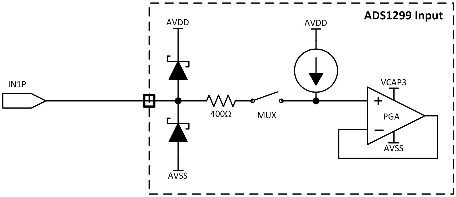
Is there some sort of series resistance inside the ADS1299 that could account for this error in measurement? Could it be a summation of the all the mux switches? I am a little confused at where this is coming from, but with the added ~600 ohms we are accurate to within +- 20 ohms on a 1K measurement, and +/- 10% accurate on higher resistances (150K).

Thank you for your help.

  • Hi Christopher,

    Thank you for your post!

    My first guess is that the AC lead-off signal is seeing some additional attenuation through the digital filter. Did you account for this already? Which AC lead-off frequency are you using: 7.8 Hz, 31.2 Hz, or fDR / 4? The exact gain of the digital filter will depend on the ratio of the lead-off current frequency to the output data rate.

    Figure 28 shows a zoomed-in plot of the sinc3 filter roll-off. From there, you can approximate the gain of the filter at your specific ratio of fIN / fDR.


    Best regards,

  • Ryan,

    Could you provide a more precise value for the gain of filter with my 7.8 Hz lead-off source, and 2K sampling rate? I am unable to determine an accurate value using the graph.

    Thank you,

  • Hi Christopher,

    I think I misread your initial post. You're saying that the calculated resistance value is ~600 ohms greater than the anticipated 1k value, correct? That's not going to be caused by the digital filter. I was concerned that you might be seeing attenuation from the filter and calculating a resistance less than the expected value. At fIN / fDR = 0.0039 (7.8 Hz / 2 kHz), the attenuation of the digital filter is negligible. 

    If you are using one of the smaller two current source magnitudes, you might be more prone to noise interference when measuring relatively small impedances. At 2 kSPS and Gain = 2 V/V, each channel on the ADS1299 is expected to have about 11.29 uVpp of noise. 11.29 uVpp / 2 / ~600 ohms = 9.4 nA. Please confirm which current source magnitude you were using for these measurements and try increasing it as much as you're allowed to do so at that frequency. 

    Best regards,

  • Ryan,

    I am using the 6 uA and 24 uA current sources. I don't see how the 11.29 uVpp could cause a ~600 ohm shift on a 5 K ohm resistor measurement. It seems like it would be more like a 1 ohm shift ((120mV - 5.645 uV) / 24uA ~= 4999 K ohm). A 14.4 mV noise would cause something like that potentially.

    It is odd, but a ~600 ohm offset gets me within +- 25 ohms on the measurement. This value works for almost an entire range of 0.5K - 150K.

    Thanks,

  • HI Christopher,

    I agree - the 11.29 uVpp of noise would account for less than 1 ohm with 6 uA or 24 uA of lead-off current. ~600 ohms out of 5k is about 12% error.

    I found some old measurements I had taken on the ADS1299EEGFE-PDK to evaluate the lead-off detection accuracy. Even after calibration, I saw similar error with the 24-uA setting. The lead-off current was measured directly with a Keithley 2401 sourcemeter while in DC lead-off current mode. I took the average of the positive and negative current sources on Channel 8 as both were used for the AC tests. I've included the measurement results below. 

    I'll ask the design team whether this 600-ohm offset could be coming from the MUX or other internal circuitry. Would you mind also sharing the input portion of your schematic from the 5k test resistor to both inputs of the measurement channel?

    ADS1299EEGFE-PDK_LOFF_Measurements.xlsx

  • Ryan,

    I am not at liberty to share the actual schematic, but I can tell you that the 5K ohm calibration resistor travels through 3 very low resistance switches (~ 3 ohms per switch), but those values are accounted for.

    The resistor is connected across the inputs of channel 1 with GROUND on the P-Input using the SRB2 switch (SRB2 is connected to ground in our design).

    I am configuring the LOFF_SENSEN for channel 1 @ 24uA.
  • Hi Christopher,

    If you prefer, you can share your schematic with me offline as well. I can email you at the email address in your myTI profile.

    How are the analog supplies configured (unipolar or bipolar)? If you remove the connection to ground on the P side of channel 1, how does that change the results?

    Regards,
  • Ryan,

    I have it configured for Bipolar.

    Removing the ground on the P side of channel 1 causes that side to be floating, and I am unable to measure the voltage drop across the 5K ohm resistor.

    Thanks,
  • Ok. So the current path is from:

    GND -> SRB2 -> IN1P -> (other stuff) -> 5k resistor -> (other stuff) -> IN1N -> LOFFN current source -> AVSS. And it sounds like you're accounting for the impedance of the "other stuff" (i.e. the MUX switches, etc.).

    The impedance in this path through the ADS1299 MUX (SRB2 to IN1P) would not account for ~600 ohms.

    Does the impedance offset scale with the lead-off current? Or is it the same whether you use 6 uA or 24 uA?

    Regards,
  • Ryan,

    That is correct on the current path.

    The offset does not scale. I keep it the same regardless of the current source. I simple add it as a series resistance to the V/IR equation.

    Thanks,
  • Hi Christopher,

    Please excuse the delay.

    I just got in touch with our analog designer for the ADS1299. He pulled up the design database and showed me that there is, in fact, an additional 400-ohm impedance in series with each input pin. You can expect a few 10s of ohms worth of additional routing, but this varies from channel to channel. 

    The 5k-10pF EMI filter on the ADS1298 was removed for this device since the impedance introduced too much noise to meet the performance targets. I'm not completely sure why the 400 ohms was kept there, possibly for protection of the internal switches. Anyway, my apologies for misleading your earlier. 

    Here's a diagram of what the input structure looks like:

    Best regards,