Because of the holidays, TI E2E™ design support forum responses will be delayed from Dec. 25 through Jan. 2. Thank you for your patience.

This thread has been locked.

If you have a related question, please click the "Ask a related question" button in the top right corner. The newly created question will be automatically linked to this question.

Data converters forum

Part Number: ADS1258
Other Parts Discussed in Thread: ADS1158

   hello:

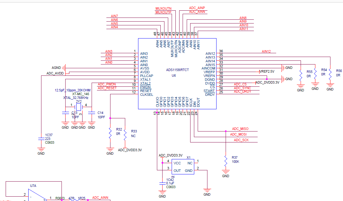
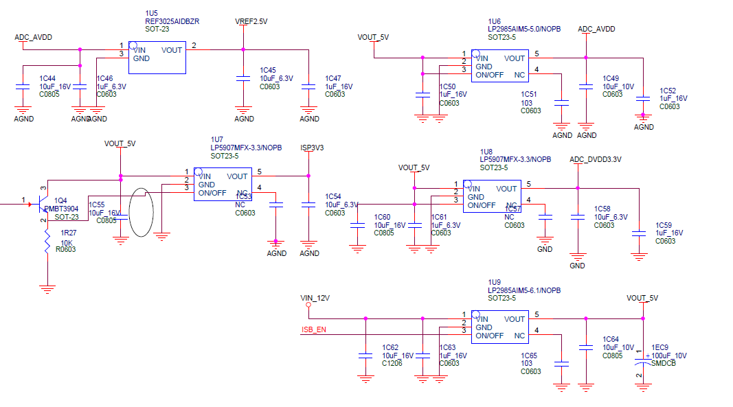
       I designed to work with a single power supply (+5v). The thermal PAD and DGND are connected together. AVSS is connected to DGND through the 0R resistor. During the process, ads1258 is often damaged. The test found that it is the dvdd of ADS1258 and The dgnd short circuit (resistance is at 47-10R) causes the SPI to be unable to communicate with the master MCU.

  • Hi Sibo,

    Welcome to the TI E2E Forums!

    I'm sorry to hear that you are having difficulties with the ADS1258. What you described for the power supply connection sounds the the correct way to connect the supplies. Do you happen to have a schematic of your circuit that you could share with us?
  • Christopher Hall said:
    您好Sibo,

    欢迎来到TI E2E论坛!

    很遗憾听到您在使用ADS1258时遇到困难您所描述的电源连接声音是连接电源的正确方法。您是否碰巧有可以与我们分享的电路原理图?

  • Hi Sibo,

    Am I reading your schematic correctly, do you have three separate ground nets?

    1. GND symbol with no label

    2. GND symbol, labeled "AGND"

    3. GND symbol, labeled "GND"

    The schematic does not show how each of these ground symbols are connected; however, more importantly than how these connection are shown on the schematic, is how you have physically connected these grounds on your PCB. The larger the return current path, the larger the impedance between these grounds, and more likely that there may be ground bounce. If ground bounce is causing the AVSS and DGND potentials to exceed the maximum difference of -2.8 to +0.3V, then this could be damaging to the device.

    I would highly recommend trying to reduce the number of different ground nets, if possible. I typically recommend using a single ground plane, see [FAQ] PCB Layout Guidelines and Grounding Recommendations for High-Resolution ADCs for more information on this topic. For the ADS1158, I would recommend connecting the AVSS and DGND pins directly together. On each of the LDOs, make sure that the decoupling capacitors on the LDO outputs are referenced to the same ground plane as the LDO's GND pin.