This thread has been locked.

If you have a related question, please click the "Ask a related question" button in the top right corner. The newly created question will be automatically linked to this question.

ADS124S08: Regulator Choice for ADS124S08

Part Number: ADS124S08
Other Parts Discussed in Thread: TPS61291, , TPS61252,

Hello:

We are currently evaluating the ADS124S08 ADC and seem to really like some of its features such as its power consumption. This ADC will be used to measure strain gauge loads and its high precision seems to be ideal. Our product is powered off of a coin cell battery (CR1225) 3V and contains a BLE transceiver. We could use 2 batteries in series if need be. I know its best to use an LDO for a regulator but because of its efficiency and the voltage drop from the coin cell(down to 2.2 volts), This is a far from ideal option for us. Even using 2 batteries in series will yield the same issue. So I have been playing around with the TPS61291 boost regulator and connected it to drive AVSS and AVDD on the ADS124S08IPBS Eval board and did not seem to see much of an increase in noise. I am concerned that I may be missing something during my testing and would like to get your opinion on this matter(in using this boost converter) prior to designing a prototype board. Please note we sell 10s of thousands of these products annually and I need to make sure I am not missing anything. If there is a better choice for our application, please feel free to make a recommendation. Your time and effort will be greatly appreciated.


Regards,

WH

  • Hi Wael,

    You have already looked at the obvious issue as the switched mode supply will have noise and ripple associated with the switching. The other not so obvious issue is the switching frequency as it relates to the modulator frequency (actual sampling frequency which is 256kHz using the internal oscillator) of the ADS124S08. You want to avoid the modulator frequency being the same, or the DC-DC converter switching frequency being a harmonic of the modulator frequency. For example, the modulator is 256kHz, so you would not want the DC-DC switching frequency to be 768kHz or 1.024MHz.

    Another concern is PCB layout. You would not want the switching supply to interact with the ADS124S08 analog inputs or to have poor grounding creating ground bounce due to the switching.

    Best regards,
    Bob B
  • Hi Bob:

    Thank you for your reply! I was not able to find any info in the TPS61291 datasheet with regards to calculating its switching frequency. Should I assume its the LC(output C) resonant frequency assuming I use the recommended L(3.3uH) and C(22uF)?

    with regards to layout, I do not plan on having the supply interact with the ADC inputs and I plan on using the ADC as differential inputs with RC filters on the input.

    In sum, Do you recommend on using this regulator or would you have any other recommendation? your time and effort will be greatly appreciated.

    Regards,
  • Hi Wael,

    I support the ADS124S08, but I do not directly support TI DC-DC converters.  You would have to ask specific questions regarding the TPS61291 on the Power Management forum.  As far as recommendations, all I can really say for sure is some customers have successfully used switched mode power supplies directly connected to the ADS124S08.  Unfortunately I cannot tell you which devices were used.  The TPS61291 appears to be a reasonable choice.

    Testing done with the ADS124S08 relates more to isolation switching supplies.  You may find this TI Design helpful:

    http://www.ti.com/tool/TIDA-01434

    The preceding TI Design uses a charge pump design to deliver a bipolar supply output and I don't think this particular device would relate well to your design.  Generally we recommend using a linear supply (such as an LDO) after the switcher to help clean up any noise artifact of the switcher.  On the ADS124S08EVM, we take the USB supply (nominal of 5V) and use a charge pump (TPS61252) to push the supply above 5.3V, then LDO the voltage back down to 5V.  We have not tried using the output of the charge pump directly with the ADS124S08.

    Regarding the TPS61291, the information I have is the same as you, which is the datasheet.  The switching frequency can possibly be derived from Figures 21 and 22 in the datasheet.

    If you have connected the TPS61291 to the ADS124S08 and have achieved acceptable performance, then you should be ok to proceed.

    Best regards,

    Bob B

  • Hello Bob:

    Can I please get the ADS124S08EVM Altium design files please. It would greatly expedite my design process. Again, your time and effort is greatly appreciated.

    Regards,
    WH
  • Hi Wael,

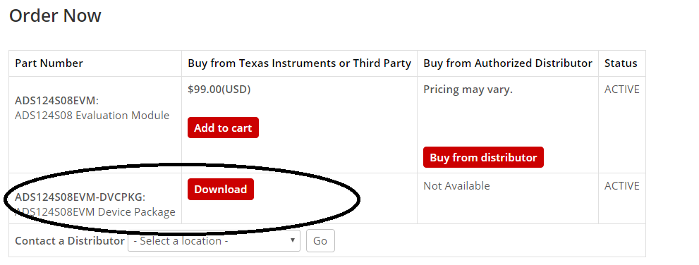
    We do not normally send out the the design files and most likely would not be all that helpful as the files are tied to a library vault that you would not have access to anyway.  The ADS124S08EVM user's guide contains the schematic, and project gerber files are a part of the software download.

    EVM user's guide:

    http://www.ti.com/lit/ug/sbau272a/sbau272a.pdf

    Software download:

    http://www.ti.com/tool/ADS124S08EVM

    The DVCPKG software installs in the Documents folder with the gerbers found at:

    Documents\DSEvalSW\Devices\ADS124S08\layout

    Symbols are available using Ultra Librarian and can be found at the bottom of the web page and downloaded from:

    http://www.ti.com/product/ADS124S08/pinout-quality

    Best regards,

    Bob B

  • Hi Bob:

    yea, I got those files. thanks for your help!

    Regards,