This thread has been locked.

If you have a related question, please click the "Ask a related question" button in the top right corner. The newly created question will be automatically linked to this question.

ADS1293: 50Hz interference problem

Part Number: ADS1293

Hi:

We used ADS1293 as the ECG sampling chip in a dynamic electrocardiogram (DCG) device.In the process of use, the following problems are found:

1. Separation problem:In the ecg sampling data record, it is found that the bias voltage of ecg signal is different in different human body or different time.It is not at the zero point (the position is random, it feels that this chip is not directly biased);But the horizontal line in the ADS1293EVM User's Guide image is at 0.Want to consult is how to achieve, we can carry on the circuit adjustment.
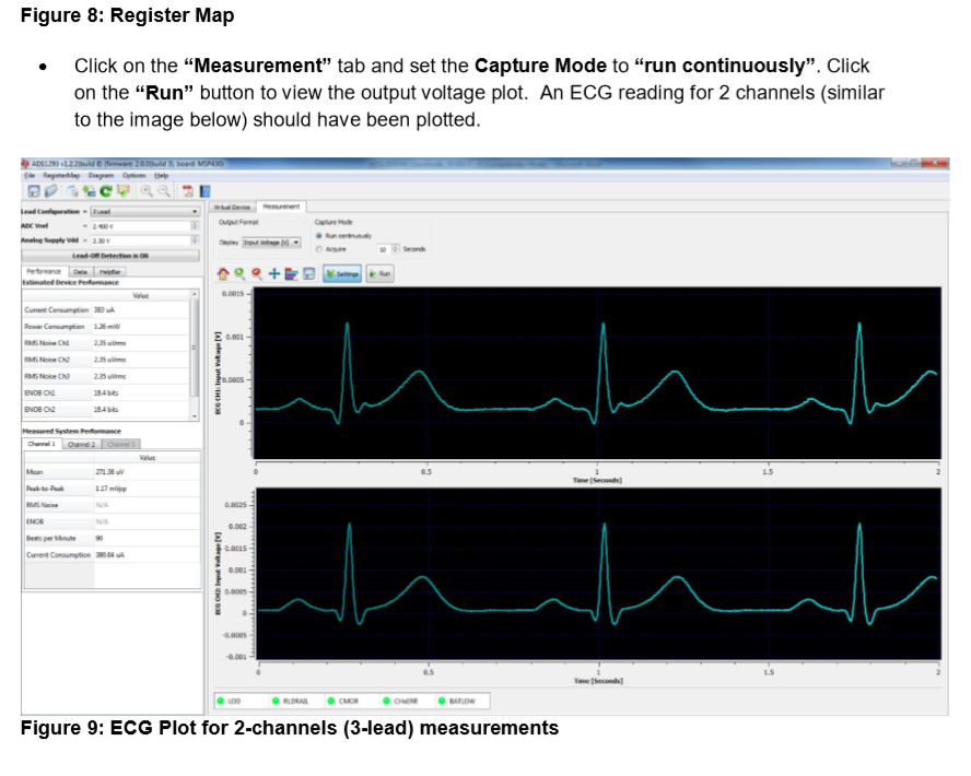
2. 50Hz interference problem

When using human test, the interference of 50Hz was found to be very serious, and the recommended solution was not found by referring to the manual of ADS1293.Want to know what good patterns can be avoided.
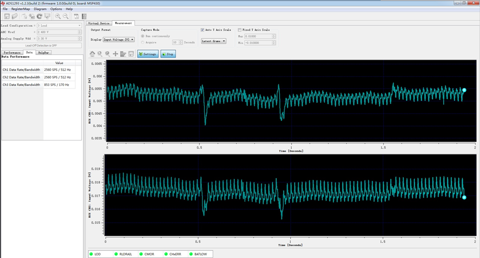
BR
Sunny

  • Hi Sunny,

    Thanks for your post and welcome to the forum.

    Are bipolar power supplies being used? If so, that would explain why it's expected for the bias voltage to be 0V.
    Remember that the bias circuit is typically fed as a combination of the inputs, so if the inputs are not static, then the bias voltage will change over time. Without having additional information (schematics, registers, waveforms) it is difficult to know what is causing the confusion/issue.

    The 50Hz issue is most likely due to not using the RLD (bias) feature of the device of the device correctly as it is meant to cancel the common-mode noise out of the measurement.

    Please see the BIOFAQ for more information regarding RLD/BIAS: e2e.ti.com/.../2855202
  • The register values for the following tests. In addition, the hardware used is ADS1293EVM (SV600846-001, Rev. B). As described in the reply, RLDIN was not short-connected to RLDREF after examination. After RLDIN/RLDREF is short connected, the ripple of 50Hz still exists, and the bias problem is not solved. Want to know how to bias the input signal in unipolar power supply to avoid baseline drift.

    address value
    0x00 0x00
    0x01 0x11
    0x02 0x19
    0x03 0x00
    0x04 0x00
    0x05 0x00
    0x06 0x00
    0x07 0x07
    0x08 0xff
    0x09 0x00
    0x0a 0x07
    0x0b 0x00
    0x0c 0x04
    0x0d 0x00
    0x0e 0x00
    0x0f 0x00
    0x10 0x00
    0x11 0x00
    0x12 0x04
    0x13 0x00
    0x14 0x24
    0x15 0x00
    0x16 0x00
    0x17 0x04
    0x18 0x00
    0x19 0x00
    0x1a 0x00
    0x1b 0x00
    0x1c 0x00
    0x1d 0x00
    0x21 0x08
    0x22 0x08
    0x23 0x08
    0x24 0x02
    0x25 0x00
    0x26 0x04
    0x27 0x08
    0x28 0x00
    0x29 0x00
    0x2a 0x00
    0x2b 0x00
    0x2c 0x00
    0x2d 0x00
    0x2e 0x33
    0x2f 0x30
    0x30 0x00
    0x31 0x00
    0x32 0x00
    0x33 0x00
    0x34 0x00
    0x35 0x00
    0x36 0x00
    0x37 0x00
    0x38 0x00
    0x39 0x00
    0x3a 0x00
    0x3b 0x00
    0x3c 0x00
    0x3d 0x00
    0x3e 0x00
    0x3f 0x00
    0x40 0xff
    0x50 0x00
    0x60 0x00
    0x62 0x00
  • Hi,

    I recommend turning off lead-off detection until the 50Hz issue is identified.

    Where are the electrodes connected on the body?
    Can you observe voltage being output on channel 4?
    What is connected to RLDIN on the EVM?

    As a reminder, the EVM is not meant for direct interface with a patient. Using a patient simulator is a more reliable way to test.