This thread has been locked.

If you have a related question, please click the "Ask a related question" button in the top right corner. The newly created question will be automatically linked to this question.

ADS1232: ADS1232 work intermittently

Part Number: ADS1232

Our customer used ADS1232 in their pressure sensor since 2014. Recently, the design has been changed (circuit design of ADC have not changed too much, and the timing of data reading has not changed), but ADS1232 work intermittently now.

1.the circuit design of ADC before

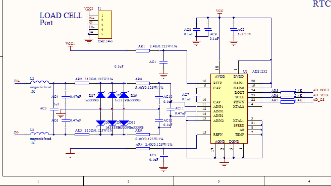
2.the circuit design of ADC now

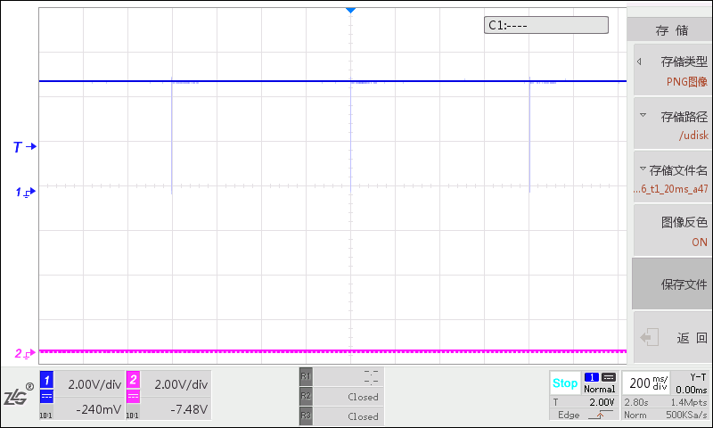
3.The waveform of 9,10 feet now(Oscilloscope 1CH is connected to CAP of ADS1232, 2CH suspended)

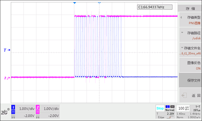
4.Timing of ADS1232(same as before)(Oscilloscope 1CH is connected to the SCLK of ADS1232, and 2CH is connected to the DOUT of ADS1232)

PS:

1. the VCC of ADS1232 is 4.85V

2.check the AC7 between 9,10 feet that capacitance is 110 nf

  • Hi Sherry,

    There are a number of differences between the 2 schematics. One difference is in the original circuit, both the analog supply and the reference were powered by the same source (VCC1), but in the new schematic the AVDD is powered by VCC and the excitation voltage/reference is powered by VCC1. You have given the voltage for VCC, what is VCC1? VCC1 cannot exceed AVDD by more than 0.1V.

    Another large difference between the 2 schematics is the input filtering. In the new schematic zener diodes are being used. Zener diodes tend to be quite leaky and will cause a measurement error. Also, there are three diodes in parallel for each input. For each additional diode there will be additional error. For fast transient protection I would recommend BAV199, and for sustained overvoltage protection I would suggest a TVS diode instead of the zeners.

    I would suggest removing the zener diodes and see if this solves the issue they are seeing. At this point it is not clear to me what the issue is as I do not know what the input voltage is at the point of measurement on the scope. The ADS1232 output is binary 2's complement, so the captured data on the scope is showing a negative code value.

    The measurement across the cap really doesn't tell me much. As I said before, I would also need to see the input voltage and the ADS1232 inputs for comparison. It may be possible that the zener diodes are pulling the analog inputs below the input range for the ADS1232. The AINP and AINN inputs must be less than AVDD-1.5V and greater than AGND+1.5V. These inputs should be measured with respect to AGND to make sure that the input is within range.

    Best regards,
    Bob B
  • Hi Bob,

    1.Such as you say, VCC1 is another power supply. The voltage of VCC1 is 4.03V and  it is not exceed AVDD by more than 0.1V. 

    2.Since customer's product is a safety device, so two parallel zener diodes are designed to construct zener clamp circuit. I'm sorry customer can't remove these zener diodes or replace them with TVS because they are recommended by the explosion proof certification authority. Although the zener diode we used will have leakage current problem, but the voltage of  AINP1&AINN1 in our product is about half of refp-refn, which is far less than 1N5339B zener voltage 5.6v. So we can accept the leakage current problem of 1N5339B.

    3.In addition, I found that: 

    It is the screenshot of oscilloscope. ADS1232 enters the OFFSET CALIBRATION.

    CH1 is connected to the DOUT of ADS1232.

    The time interval of two AD conversion is 800ms, which accord with the timing of offset calibration. I can't understand how 25 SCLK can lead to this situation.

  • Hi Sherry,

    It does look like the ADS1232 is going into offset calibration mode. This would explain why the CAP voltage goes to zero.

    Would it be possible to probe the SCLK pin on the ADS1232 (or as close to it as possible) to see if perhaps there are any signal integrity issues with SCLK?

    Also, do you have the ability to reduce the SCLK frequency to see if the issue goes away with a slower SCLK?