This thread has been locked.

If you have a related question, please click the "Ask a related question" button in the top right corner. The newly created question will be automatically linked to this question.

ADS1298: SPI communication

Part Number: ADS1298

Hello,

I have been trying to connect the ADS1298 with an ODROID C1 through SPI. I have the 4 SPI channels and 2 signals for the Reset and the Start pins.

I have issues with the actual sending of the commands SDATAC and the read ID, also with sending the START but I can go arround by connecting it to one of the GPIO pins of the ODROID and driving it HIGH or LOW.

My code is bellow I hope you can help me.

I have verified steps 1, 2, 4, 5 and 6 in [FAQ] ADS129x: How do I verify that my ADS129x device is still functional?; and steps 1 and 2 in [FAQ] ADS129x: I'm having trouble communicating with my ADS129x device via SPI. What debug steps I should try?. AdditinallyI know the SPI communication is working since I verified that when the MOSI and MISO channels were connected together the messages were passing correctly.


Thank you very much for your time in advance and if there is any extra info you need ask me please,

Best,

Sofia

import os
import time
import RPi.GPIO as GPIO
import wiringpi

wiringpi.wiringPiSetupGpio()    # For /sys/class/gpio with GPIO pin numbering

START = 0x08
SDATAC = 0x11
RREG = 0x20
ID = 0x00

channel = 0
speed = 3906250
mode = 1

Fd = wiringpi.wiringPiSPISetupMode (channel, speed, mode)
print Fd

### Reset pin High ###
wiringpi.pinMode(100, 1)       # Set pin 6 to 1 ( OUTPUT )
wiringpi.digitalWrite(100, 1)  # Write 1 ( HIGH ) to pin 6
pin = wiringpi.digitalRead(100)      # Read pin 6.
print pin

time.sleep(0.5) # secs  --> tPOR > 2^18tCLK; internal fCLK = 2.048 MHz; tPOR = 0.128sec

### Reset pulse ###
wiringpi.pinMode(100, 1)       # Set pin 6 to 1 ( OUTPUT )
wiringpi.digitalWrite(100, 0)  # Write 1 ( HIGH ) to pin 6
time.sleep(0.1) # secs --> sleep >2xtCLK; internal fCLK = 2.048 MHz; tRST = 0.0000009765625sec
wiringpi.digitalWrite(100, 1)  # Write 1 ( HIGH ) to pin 6
time.sleep(0.1) # secs  --> sleet tRST - 18 tCLKs; 18 tCLKs = 000000087890625sec


#########Setting SPI communications#######
#### Registers can then be writen ####
print "SDATAC Command"
buf = bytes([SDATAC])
SDATACreturn = wiringpi.wiringPiSPIDataRW(channel, buf)
print SDATACreturn
time.sleep(0.5)

print "START Command"
wiringpi.pinMode(116, 1)       # Set pin 6 to 1 ( OUTPUT )
wiringpi.digitalWrite(116, 1)  # Write 1 ( HIGH ) to pin 6
time.sleep(0.1) # secs --> sleep >2xtCLK; internal fCLK = 2.048 MHz; tRST = 0.0000009765625sec

buf = bytes([RREG, ID])
ID_return = wiringpi.wiringPiSPIDataRW(channel, buf)
print ID_return

[FAQ] ADS129x: I'm having trouble communicating with my ADS129x device via SPI. What debug steps I should try?

  • Hello Sofia,

    Thanks for your post!

    Can you verify on a scope or logic analyzer that you are sending the SDATAC command correctly?

    When it comes to multi-byte commands, make sure that you are following the tSDECODE requirement, which basically specifies the minimum time it must take to send one byte. I can help you confirm this if you tell me your SCLK frequency.

    Best regards,
  • Hi Ryan,

    Thank you very much for your reply,

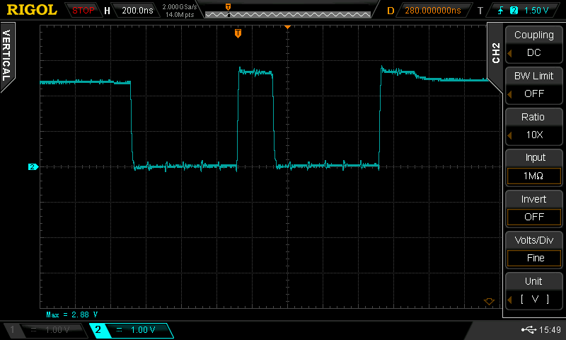
    The SDATAC signal is as in the image.

    The SCLK is being set to speed = 3906250 Hz.

    And the results I am getting for the RREG and ID are '\x00\x01'.

    Thank you very much,

    Best,

    Sofia

  • Sorry,

    The image was not attached. Signal issued when the SDATAC signal is imited.

    Update I managed to send START code which was verified with the DRDY signal wich started a square wave.

    The results I got for RREG, ID were \x00\x00. Do you have any sugestion on what can be happening?

    Best,

    Sofia

  • Hi Sofia,

    Sorry I should've been more clear about the image I was requesting. Can you capture /CS, SCLK, and DIN when you send the SDATAC command? I wanted to check the relevant timing. However, I would guess that the small glitches in the waveform align with each edge of SCLK (first glitch = first SCLK falling edge). It appears you're sending 0x11 correctly.

    Following SDATAC, you mentioned that you can send the START command? Can you also send the STOP command? If the start pin is low, the START and STOP SPI commands can be used to enable / disable conversions. You'll notice /DRDY stops pulsing when conversions are stopped.

    If START and STOP commands are also working fine, then the issue is only with the RREG command. Please share a scope capture of this command and the subsequent response on DOUT. You will have to send 0x20 0x00 0x00 (the last 8 bits are an extra "no-operation" command just to clock out the 8 bit register data from the ID register). Can you share a scope capture of /CS, SCLK, DIN, and DOUT when you send this command?

    FYI - 8 bits sent at 3.906250 MHz will take 2.048 us. If you are using the internal master clock, the tSDECODE requirement is 4*tCLK = 1.96 us, so you do not need to add extra time to meet this requirement.

    Best regards,

  • Hi Ryan,

    Thank you very much for your reply, I have managed to read the ID of the ADS1298, I think the extra "no-operation" command did the trick I am now getting the ID as 0x92

    I am now trying to do the "Initial Flow at Power Up"

    But for sending the Command WREG CONFIG3 0xC0 what exactly do I need to write?
    WREG, 0x01, CONFIG3, 0xC0 --> 0x40 0x01(for sending 1 command) 0x03 0xC0; do I need any time for sending or processing the signals?
    Do I need also to send the extra "no-operation" command for this register?

    Thank you in advance,
    Best,
    Sofia
  • Hi Sofia,

    The command to write the value "0xC0" to one address (n-1 = 00h) with address 03h (CONFIG3) is:

    0x43 0x00 0xC0

    Best regards,