This thread has been locked.

If you have a related question, please click the "Ask a related question" button in the top right corner. The newly created question will be automatically linked to this question.

ADS1292R: Only noise when reading from channel 2

Part Number: ADS1292R

Hi all!

I am currently interfacing the ADS1292R with an ARM BLE chip (SPBTLE-1S). I am able to read/write to registers and also read the data in continuous mode with the 1 Hz test signal. The PCB layout is the following:

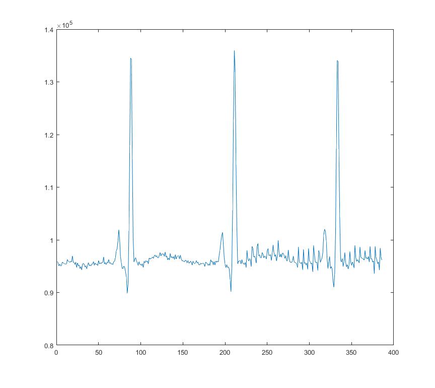
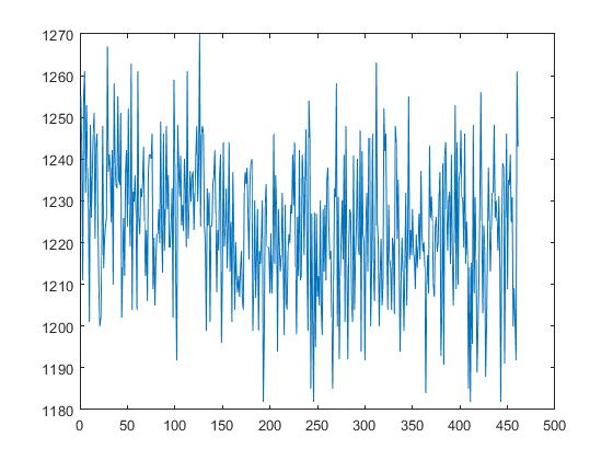
Unfortunately, when testing with a clean 1Hz sin wave from a signal generator, the signal recorded is completly noisy. Any idea as why that would be the case? This is my register configuration: 

temp=0x00; //0x00
ADS1292R_IO_Write(&temp, ADS1292R_REG_CONFIG1, 1); //Set sampling rate to 125 SPS

temp=0xA0; //0xA0
ADS1292R_IO_Write(&temp, ADS1292R_REG_CONFIG2, 1); //Internal reference

temp=0x10; //0x10
ADS1292R_IO_Write(&temp, ADS1292R_REG_LOFF, 1); //Lead-off defaults

temp=0x00; //0x00
ADS1292R_IO_Write(&temp, ADS1292R_REG_CH1SET, 1); //Channel 1 power on

temp=0x00; //0x00
ADS1292R_IO_Write(&temp, ADS1292R_REG_CH2SET, 1); //Channel 2 power on

temp=0x0C; //0x0C
ADS1292R_IO_Write(&temp, ADS1292R_REG_RLDSENS, 1); //RLD settings: fmod/16, RLD enabled, RLD inputs from Ch2 only (no RLD buffer)

temp=0x00; //0x00
ADS1292R_IO_Write(&temp, ADS1292R_REG_LOFFSENS, 1); //LOFF settings: all disabled

temp=0x00; //0x00
ADS1292R_IO_Write(&temp, ADS1292R_REG_LOFFSTAT, 1); //LOFF settings: all disabled

temp=0xC2; //0xC2
ADS1292R_IO_Write(&temp, ADS1292R_REG_RESP1, 1); //Respiration: MOD/DEMOD turned only, phase 0

temp=0x03; //0x03
ADS1292R_IO_Write(&temp, ADS1292R_REG_RESP2, 1); //Respiration: Calib OFF, respiration freq defaults

temp=0x0C; //0x0C
ADS1292R_IO_Write(&temp, ADS1292R_REG_GPIO, 1); //Respiration: Calib OFF, respiration freq defaults

Thank you,

Xavier

  • Hi Xavier,

    Welcome to our forum and thank you for your post!

    Verify that the amplitude of the input signal is within the measurable range of the ADC. It must be greater than the ADC noise floor at that data rate / PGA gain setting combination (see the Noise Measurement tables) yet smaller than the maximum differential input voltage (+/- VREF / PGA gain). Also, the common-mode voltage of the input signal must be shifted such that the absolute voltage does not exceed the analog supplies.

    The ground connection of your signal source must be shared with the ground of your ADS1292R circuit. Verify that the signal looks correct at the ADS1292R input pins using an oscilloscope.

    Best regards,
  • Hi Ryan,

    Thank you very much for your reply! Any help is very appreciated.

    As you asked, I was able to verify an adequate signal on the ADS1292R input pins when generating a 1Hz 150mV peak-to-peak square signal. The common-mode voltage was about 25mV.

    While in debug mode (Keil v5), I am happy to say that I am able to properly read the 1 Hz signal using the ADS1292R. Oddly enough, if I exit the Keil debug mode and perform a SPBTLE-1S core reset and then proceed to display the signal's values, only noise is measured.

    I tried the same thing again with the embedded 1Hz signal and I am able to read it in both debug and during normal operation. Although, in normal operation (meaning after a normal SPBTLE-1S core reset), the amplitude of the signal is smaller by a factor of ~10x.

    Cheers,

    Xavier

  • Hi Ryan,

    Upon further investigation, I realised there was an issue with my register read command. After fixing the issue and removing C20 and C19 I am able to have a somewhat clear ECG signal! I am uploading my schematic again since it seems there was an issue with the previous upload:

    Here is the ECG signal when the electrodes are connected directly to 1N2P and 1N2N:

    This is the signal when the C19 and C20 capacitors are soldered back on the board with both channel 1 and respiration disabled:

    And now this is the signal with both capacitors on the board with channel 1 and respiration enabled. I also added the respiration signal:

    Any idea what could cause the noise when soldering the C19 and C20 capacitors? Why would enabling channel 1 and respiration cause even more noise? 

    Thank you very much for you time,

    Xavier

  • A bad solder was causing the issue. Everything works fine now.

  • Xavier - thanks for the update, we're glad you figured out the root cause of the issue!

    Best regards,