This thread has been locked.

If you have a related question, please click the "Ask a related question" button in the top right corner. The newly created question will be automatically linked to this question.

ADS52J90: Simplified driving Single-Ended with reduced dynamic range BW: DC to 10MHz

Part Number: ADS52J90
Other Parts Discussed in Thread: AFE5851, AFE5832LP

Hello,

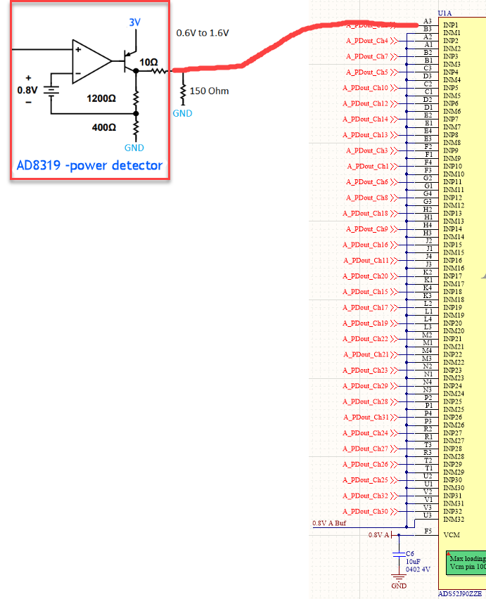
I'm using QTY: 32 ADS52J90 for 1024 single-ended channels. Need bandwidth from DC to 10MHz. I'm ok with dramatically reduced dynamic range from ADC.

Goal is to minimize components needed. Don't have space/budget/power for op-amp SE to DE conversion. 

1.  Will setting the negative input of ADC channels to 0.8V be the best value (since datasheet says VCM 0.7 to 0.9V) with an 0.6 to 1.6V input on the positive pin input? (I realize that the Common mode will be way off)

2. Would 1.2V be a better voltage to apply to the negative input pin ? (datasheet doesn't say this, but I'm ok with dramatically reduced dynamic range)

3. Does adding distributed capacitors say 1uF on the negative input pins add any benefit to noise reduction and and series resistor (say 5Ohm) to each negative input?

4. Circuit (power detector output) connected to ADC is about 3 inches away. What additional components can be added to reduce noise and bandwidth to 10MHz?

5. Please email at regank33@gmail.com to further this discussion as needed. 

Thank you and see below for diagram. 

  • Great to see high channel count usage. 

    VCM can be 0.8V as the typical value. when you connect the negative side as 0.8V , you will get the symmetric waveform as 1Vpp or +/-0.5Vp.  if your signal is a asymetric, then you can bias the negative side to a different voltage. your signal seems to have a different VCM as ADC's. i would suggest the AC coupling. while you will lose the DC information. may be you can adjust the 150ohm resistor's GND pin to a different voltage, then we can bring the VCM from 1.1V to 0.8V as well? 

    adding caps on INM pin is good idea to filter out some high freq noise. 3 inch trace should be OK. we have see longer traces. as long as it has a good sloid GND plane under it. 

    Please note, we also have 16CH ~ 32CH AFEs to accept the single ended signals. you can refer to AFE5832LP or AFE5851. 

    Thanks!

  • Hi thank your for your answers.

    Can you answer all my questions thoroughly?

    I need serious answers for this as I will be using thousands of these parts.

    I can't call texas instruments since they don't support engineers like most other semiconductor companies do.

    Those other two ADC's you menntioned are too expensive as current ADC offers more value.

    Kevin

  • i quoted the previous questions. hope it is more clear. 

    I recommend you test EVM for connecting your sensor circuits before final circuit . 

    if AFE chips fit the applicaiton better for tech reasons, you can discuss the price with your dist or sales. we hope you get the best performance system. 

    Thanks!

    1.  Will setting the negative input of ADC channels to 0.8V be the best value (since datasheet says VCM 0.7 to 0.9V) with an 0.6 to 1.6V input on the positive pin input? (I realize that the Common mode will be way off)

    VCM can be 0.8V as the typical value. when you connect the negative side as 0.8V , you will get the symmetric waveform as 1Vpp or +/-0.5Vp or datasheet said  VCM – 0.5 to  VCM + 0.5

     your signal seems to have a different VCM as ADC's. i would suggest the AC coupling. while you will lose the DC information. 

    may be you can adjust the 150ohm resistor's GND pin to a different voltage, then we can bring the VCM from 1.1V to 0.8V as well? 

    2. Would 1.2V be a better voltage to apply to the negative input pin ? (datasheet doesn't say this, but I'm ok with dramatically reduced dynamic range)

    when you connect the negative side as 0.8V , you will get the symmetric waveform as 1Vpp or +/-0.5Vp.  if your signal is a asymetric, then you can bias the negative side to a different voltage.

    3. Does adding distributed capacitors say 1uF on the negative input pins add any benefit to noise reduction and and series resistor (say 5Ohm) to each negative input?

    adding caps on INM pin is good idea to filter out some high freq noise as a filter. 5 ohm may not be nesscary. 

    4. Circuit (power detector output) connected to ADC is about 3 inches away. What additional components can be added to reduce noise and bandwidth to 10MHz?

     3 inch trace should be OK. we have see longer traces. as long as it has a good sloid GND plane under it.  you will need passive BP fitler since you don't have room for opamp.