This thread has been locked.

If you have a related question, please click the "Ask a related question" button in the top right corner. The newly created question will be automatically linked to this question.

ADS131A04: Accurate sampling start time in asynchronous Interrupt mode

Part Number: ADS131A04

Hi Team,

Now there is an application which need to know the sampling start time, however, there is no accurate start time for the each sampling period. Is it possible to use the /DRDY signal in asynchronous Interrupt mode from ADS131A04 to calculate the first sampling start time?

I would explain the idea in details:

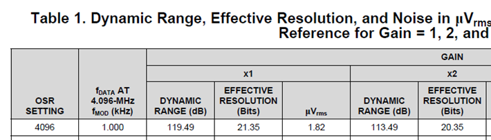
1. fDATA is 1kHz, fMOD is 4.906MHz and OSR is 4096.

2. Asynchronous Interrupt mode is used between ADS131A04 and MCU.

3. When the /DRDY transients from high to low, MCU reads the /IRQ and record the time to be T.

 /DRDY transiting from high to low means the conversion is finished, it's known that there were 4096 samples for this conversion, so the total time would be about 1ms(1/4.096MHz*4096=1ms), so the first sampling start time for this conversion would be (T-1ms). Is it correct?

If it's correct, it's known that each sampling time is 0.244us (1/4.096MHz=0.244us), so the error is 0.244us, the accurate start time would be (T-1ms)±0.244us, is it correct? If not, could you please help tell what's the error for the time?

Our accuracy for the first sampling start time of each conversion is ±10us. If my thought is not correct, could you please tell if there is any way to know the accurate start time?
Thanks and Best Regards!

Hao

  • Hello Hao,

    Our primary support engineer is out of the office today.  Expect a response Monday or Tuesday next week.

  • Hi Collin,

    Could you please help assign this thread to our primary support engineer today? Thanks!

    Best Regards!

    Hao

  • Hao,

    I'll need to do a little research about this post. While the amount of time that you relate between fMOD, fDATA, and OSR are correct, there is a little more time or latency to get the data. There is some time required to take accumulation from the modulator output to convert this to data. I'll need to check on this timing and I'll get back to you tomorrow.

    Joseph Wu

  • Hao,


    I was able to talk to one of the digital designers today, and there is more to the latency of the ADC data than I had realized. There are a couple of parts to this and I'll go through each one separately.

    First, this device uses a sinc^3 filter. This means that the output data is a moving average of three output data. If the device is running at 1kSPS as you mentioned in the example case, that would mean that it would take 3 samples of data to fully settle out the output data. For example if the ADC starts a conversion and the analog input saw a step function at the same time, the it would take 3 conversion cycles to see fully settled data. The first two conversions would still see the change, but it wouldn't be fully realized until the third conversion.

    Second, the output of the ADC is buffered. This output data is buffered for an entire conversion cycle before it appears on DOUT. Because of this, the first fully settled conversion isn't available until the fourth falling edge of /DRDY. This means that fully settled data cannot be read until after 4ms after the first start of the conversion (assuming a 1ms data period).  This is briefly discussed in Conversion Mode (Page 35, section 9.9.4) and is also very briefly discussed in "Accounting for delay from multiple sources in delta-sigma ADCs" (only at the very end, just before the summary), which can be found here:


    There may also be several modclk period of time as the ADC takes the accumulated output of the modulator and converts that to an output data. This amount of time scales the output to the proper full scale, and removes any offset from the conversion. However, a fully settled output data is only found after the equivalent of four data conversion periods.


    Joseph Wu

  • Hi Joseph,

    Asynchronous interrupt mode is used and /DRDY will be the interrupt signal to MCU, when /DRDY transients from high to low, it means that the conversion is settled out, according to your explanation,  the total delay should be ≈4ms, the error should be the total delay which maybe within 2 output samples(2ms)(there should be some margin compared with the result in the app note). Is it correct? If so, the error seems to be much larger than 10us resolution, it will not meet the requirement...

    Thanks and Best Regards!
    Hao

  • Hao,


    Exactly what is your customer concerned about? Are they concerned about the exact timing from the start of the conversion to the time that the /DRDY indicates that the conversion is finished? This time should be the same each time a conversion is started. This is the same number of clock cycles for each conversion.

    However, if they care about the latency of the reading, (which is the long amount of time between the start of the conversion and the time it takes to get fully settled data), this should be 4ms at 1kSPS. This includes 3 conversions with the sinc3 filter and one other conversion period for the data buffer. Then this long delay would be a problem with this device.


    Joseph Wu