This thread has been locked.

If you have a related question, please click the "Ask a related question" button in the top right corner. The newly created question will be automatically linked to this question.

ADS1298: How to properly use the RLD functionality

Part Number: ADS1298

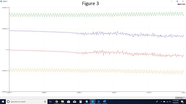
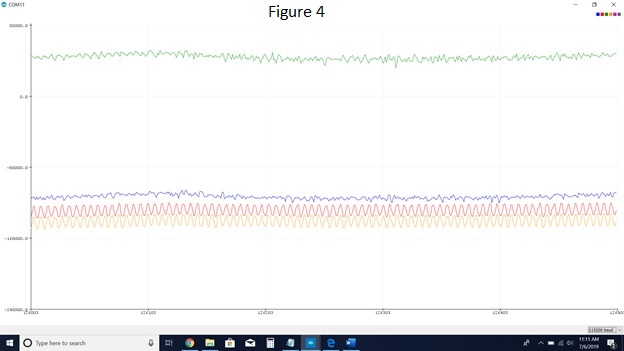
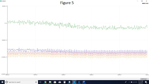
I am having problems with the RLD drive system. I am able to read signals, both computer generated and human generated. The issue I am having is that I have a lot of noise (possibly 60Hz noise) when I'm reading, and patient movement also generates a significant amount of noise. I read through the documentation for RLD drive, but I'm still missing some of the "how-to". I would like to use the RLD drive to get rid of the extra noise in my system.

Questions:

  1. To use RLD drive, should I be concerned with the CONFIG3 register or RLD_SENSP and RLD_SENSN registers?
  2. What settings should I put each channel in (in the CHnSET)?
  3. What channels should I have electrodes in?


Clarifications/Where I'm at:

  • I will be using all the electrodes on the patient's forearm.
  • I am using an ADS1298.
  • I can easily read and write to registers.
  • I am using an Arduino Due.
  • I would like to use as many channels as possible.
  • Hi Spencer,

    Thanks for your post and sorry for the delay! 

    The RLD drive can help with the 60Hz noise, but will probably not help with patient movement. To provide a quick summary, the RLD voltage can be a summation of the input channels that you select, or can be selected to be mid-supply. Using the RLD ensures that the measurement from the electrodes is within the common-mode range of the PGA, and ideally cancels much of the noise through common-mode rejection at the PGA. 

    1. Both. CONFIG3 is used for basic RLD amplifier operation. Things like is the RLD amplifier turned on, is the electrode connected, are you generating the RLD voltage from electrodes or using mid supply. RLD_SENSP/N will let you decide which (if any) of the inputs you would like to include in the summation for RLD. 

    2. Normal operation, whatever gain you need (higher is better to take advantage of the full-scale range - without clipping of course), and normal electrode input. It is also possible to route the RLD signal through one of the normal electrodes in the event that the RLD electrode becomes disconnected from the patient, but let's not worry about that for now. 

    3. That's really up to you. What type of measurement is being performed? What do you want to accomplish with this measurement? 

    I recommend checking out this video series: https://training.ti.com/how-measure-ecg-guide-signals-system-blocks-and-solutions

    and take a look at the BIOFAQ in my signature for the common-mode rejection app note under more collateral. 

  • Mr. Smith,

    Thank you for the response!

    Upon looking over the documentation, I still have some questions.  

    1) As far as common-mode rejection (CMR), does that take place through an electrode connected to RLD_OUT?  Or where do I send that CMR signal?  Is this the signal I can also send through a different electrode in case the RLD electrode becomes disconnected? (I care less about the RLD becoming disconnected and more about how to send RLD_OUT through a different channel).

    2) What is the purpose of CONFIG3 bit 4? (RLD_MEAS)

    3) If I have RLD_SENSP and RLD_SENSN at 0x00, do I have any RLD signal?  Or is it this that explicitly generates the signal?

    Clarifications:

    • I am trying to get EMG data from a forearm, and therefore all the electrodes will be on the forearm.
    • I will, in theory, be using this to control prosthetics.
    • I was able to watch the entire video series and read some of the extended documentation in the BIOFAQ.

    Thank you again for all your help.  

    Best,

    Spencer

  • Hi Spencer,

    Happy to help! 

    1. Yes, the electrode is commonly referred to as the Right Leg Drive electrode. So for standard 3 lead ECG systems, you are taking measurements on Right Arm, Left Arm, Left Leg, and then you have the Right Leg Drive electrode which is driving the common-mode signal. This is correct - take a look at figure 34. in the datasheet. 

    2. Sometimes it's helpful to measure the RLD/common-mode signal that is being applied to the patient. It can be used as a sanity check that things are enabled/biased properly. 

    3. Looking at figure 34... you can either generate the RLD signal as a summation of the electrode measurements using RLD_SENSP and RLD_SENSN or mid supply using RLDREF_INT. I don't have a lot of experience with EMG, so I would recommend trying out both to see which one yields better common-mode rejection. Theoretically I don't think there will be much of a difference, but I've been surprised before. 

    Sounds like a really cool project and happy to hear that the BIOFAQ was helpful! 

  • Mr. Smith,

    Thanks for responding via my number system.  It helps keep track of whether questions are answered or not.

    When I look at figure 34 in the datasheet, I see RLD_OUT going into RLD_IN.  After RLD_IN, I see it essentially replacing IN8P and IN8N electrodes so you can read the signal.

    I'm hoping to use the RLD signal to help get rid of 60 Hz noise, but my current board doesn't offer access to RLD_OUT.  I don't fully understand the RLD signal and how to use the electrode.

    1) Is the RLD electrode an input or an output for my device?

    2) If I understand the process correctly, I take the RLD signal, apply it to the patient via the RLD electrode.  This helps eliminate 60 Hz noise.

    Is 2) correct?  Or am I missing how the RLD_electrode works?

    3) Is there a way to send the signal through a different pin besides RLD_OUT?   I thought in an earlier post (of yours) that it was possible to send this signal out a different channel.  Is this shown in figure 33?  MUX bits either 110 or 111?

    Thanks for your help in this project and your timely responses.

    Best,

    Spencer

  • Hi Spencer,

    1. The RLD electrode is an output. 

    2. Correct.

    3. The signal still needs to come out of RLD_OUT so that the RC filter can set the phase of the signal. You can either connect the RLD_Electrode here or route it to be an output from one of the input channels using the MUXchX[2:0] registers. This is shown in figure 33. 

    Happy to help! 

  • Mr. Smith,

    The following is a sampling of data using all the information we've talked about.

    I believe that the red data is correct EMG data.  However, I cannot figure out why the other 3 channels shown seem to not follow the same pattern.  The channels shown are channels 1-4.

    My registers read the following in hexidecimal...

    CONFIG 1 85
    CONFIG 2 10
    CONFIG 3 E4
    Channel 1 00
    Channel 2 00
    Channel 3 00
    Channel 4 00
    Channel 5 06
    Channel 6 00
    Channel 7 00
    Channel 8 07
    RLD_SENSP 07
    RLD_SENSN 07

    I'm trying to generate an RLD signal based off an average of the first three channels.  I think I have CONFIG 3 correct.

    Any thoughts on the rest of the signals?

    Thanks,

    Spencer

  • Hi Spencer,

    Where exactly are the electrodes connected on the body? 

    If you change their position, Ie swap channel 1 and 4 do you see the same signal pattern? 

    I would like to know if this is a channel configuration or an electrode location issue. 

    How does it look if you change CONFIG3 to EC to generate the RLD signal internally?

  • Mr. Smith

    I use a sleeve of 34 electrodes which are spaced most places on the forearm. I can essentially use any for a set of differential pairs. My current setup involves using one electrode near the elbow/ulna as my RLDOUT signal (Currently channel 8 N). Another electrode near the elbow/ulna is the Negative IN for channels 1-7. The other electrodes are placed sporadically around the forearm in no particular order (and I can move them to more or less any location around the forearm).
    The following series of figures shows data I collected in one sitting. Figure 1 shows the noise when connected to an AC power source. I then disconnected my laptop from the wall for the remaining figures.

    Figure 2 shows that when using CONFIG 3 = 0xE4.
    Figure 3 shows that at some points, I can get two channels working.
    Figure 4 shows that without any further commands to anything, the two channels can change.
    Figure 5 shows that when a channel drifts into another channel (or area), it changes from good EMG data to noise.
    Figure 6 shows that one of the two channels has been lost to noise.
    Figure 7 shows that all the channels have been lost to noise (because of the drift mentioned in figure 5).
    Figure 8 shows a different two channels with good EMG data.

    I feel as if I have tried several different channel settings for both the configs and the channels themselves.
    If you have any suggestions, I would happily take them. In the meantime, while I wait for your response, I will more heavily document any patterns I can find.

    1. Is there a good way to reduce drift?

    Thank you for your extended help in understanding RLD with the ADS1298.

    Best,

    Spencer

    Figure 1

  • Hi Spencer, 

    Very interesting application. No rush, but when you get the chance if you could re-post the pictures that would be great. 

    What kind of drift are you referring to? Is the DC level of the signal slowly changing over time? 

    Try placing the RLD electrode in a more central location and see if that helps. 

  • That's odd the pictures only semi-uploaded.  I'll give it another shot.

    The drift I'm referring to I believe is DC offset, but it can move significantly over the course of 5 minutes as you'll see from the figures.

    I'll move the RLD and see if it changes anything.

    Thanks,

    Spencer

  • Hi Spencer,

    It happens. 

    Alternatively, you may want to try blue-wiring a mid supply common-mode configuration like what is depicted in this post:

  • Mr. Smith,

    Thanks for your help with the RLD drive.  I've decided to end this forum, and once I have some clearer questions, I'll post them under a new subject.

    Thank you for taking the time to explain and answer questions.

    Best,

    Spencer