This thread has been locked.

If you have a related question, please click the "Ask a related question" button in the top right corner. The newly created question will be automatically linked to this question.

ADS1235 AC-excitation

Other Parts Discussed in Thread: ADS1235

Hello. I have some questions about ADS1235.

I want to use 2-wire mode AC-excitation. In this mode use PINs: AIN0 and AIN1 (or GPIO0 and GPIO1, or inverse ACX1 and ACX2). I want to understand the momentary status of the outputs (inverse ACX1 and ACX2) during one conversion phase (the voltage polarity is normal) and for the alternate conversion phase (the voltage polarity is reversed).

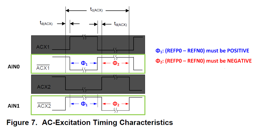
phase 1 (1 conversion): inverse ACX1=high, inverse ACX2=low;

phase 2 (2 conversion): inverse ACX1=low, inverse ACX2=high

or

phase 1 (1 conversion): inverse ACX1=low, inverse ACX2=low;

phase 2 (2 conversion): inverse ACX1=high, inverse ACX2=high

???

Or do I manage the state of the inverse ACX1 and ACX2 outputs by writing to the registers? 
How to control the outputs of the ACX pins (ADS1235 or external MCU by writing to the registers of ADS1235)?

  • Hi Alexander,

    Welcome to the TI E2E Forums!

    Here is a Figure from the datasheet which I've annotated to distinguish between the phases:

    • Between phases, the non-overlapping /ACX1 and /ACX2 will both be high.
    • In phase one /ACX1 will go low (and /ACX2 remains high).
    • Between phase one and two, /ACX1 will return high
    • In phase two /ACX2 will go low (and /ACX1 remains high)

    When AC-excitation mode is enabled the GPIO pins will be automatically controlled, and the ADC will provide averaged conversion results of phase one and phase two measurements. If you'd prefer to control the GPIO pins yourself, then you would not enable the AC-excitation mode and manually write to the GPIO registers to control these signals in a similar manner as described above.

    I hope that helps!

  • Christopher, thank you very much for your explain.