This thread has been locked.

If you have a related question, please click the "Ask a related question" button in the top right corner. The newly created question will be automatically linked to this question.

ADS1232: ads1232

Part Number: ADS1232

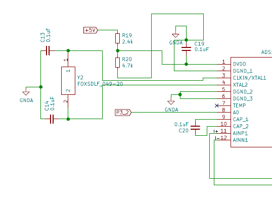
 This is the schematic and i select the datarate speed is 10 sps  when i probing the adc dout pin it shows only high (+5V)  and AVDD and DVDD are both working in 5V logic ,and i conformed that when i probing the crstal pin usind dso it doesnt show any waveform.please help me to slove the problem it is very urgent..

                                                                             thank you....

  • Hi Gobinath,

    Initially you said you were using an oscillator, but I see in your schematic you are using a crystal.  Is there a reason why you want to use a crystal instead of the internal oscillator of the ADS1232?  The internal oscillator is used if the CLKIN pin is set to ground and no external crystal is needed in this case.

    As far as the crystal, it will never start will such high cap loading.  Normally this would be around 10pF for C13 and C14.  For effective crystal oscillation to start you need to be very careful with routing, cap placement and cap value.  The cap value chosen depends on the crystal and any capacitance in the path of the crystal to the ADS1232.  The crystal datasheet should show you the capacitance load, but you could try 10pF to see if it starts.

    Another thing I noticed is you are attempting to power the DVDD portion using a voltage divider.  You make an assumption that all you need at this pin is a voltage, but the device power pins require a low impedance source.  DVDD will draw periodic short duration current that can be quite large.  This can make the voltage sag at the pin at the times of the of current demand.  The result is an unstable device with unpredictable results.  At the very least you would need a large bulk capacitor (100uF or more) near the DVDD pin to hold charge when current demand requires it.  Even then, this may not work.  It would be much better to use a regulating source, such as an LDO regulator, or even a shunt regulator (zener diode).  An LDO is the preferred method.  Is it not possible to use the same voltage source as the micro?

    You should also control the PDWN pin.  The PDWN pin must stay low until the AVDD and DVDD supplies are nominal.  You can then pull PDWN high, but I would suggest that you also pulse the PDWN to reset the device just to make sure there were no issues using the powering method chosen.

    So I suggest setting the CLKIN pin to ground instead of using the crystal and replace the voltage divider input for DVDD with a true regulated low impedance source.

    Best regards,

    Bob B