Other Parts Discussed in Thread: ADS1292
Hi,
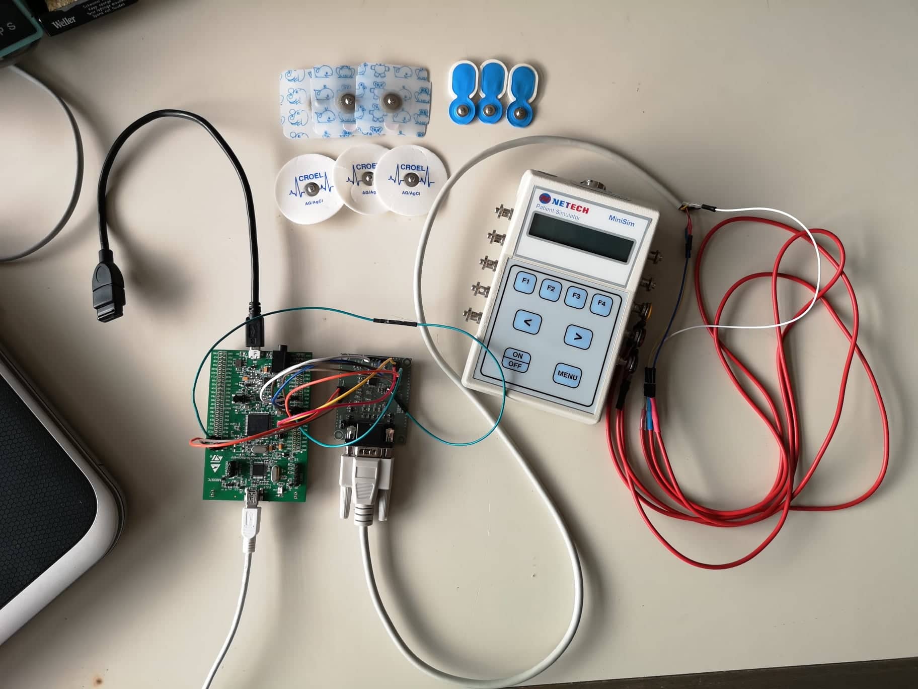
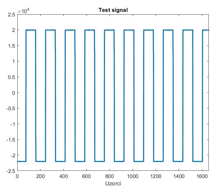
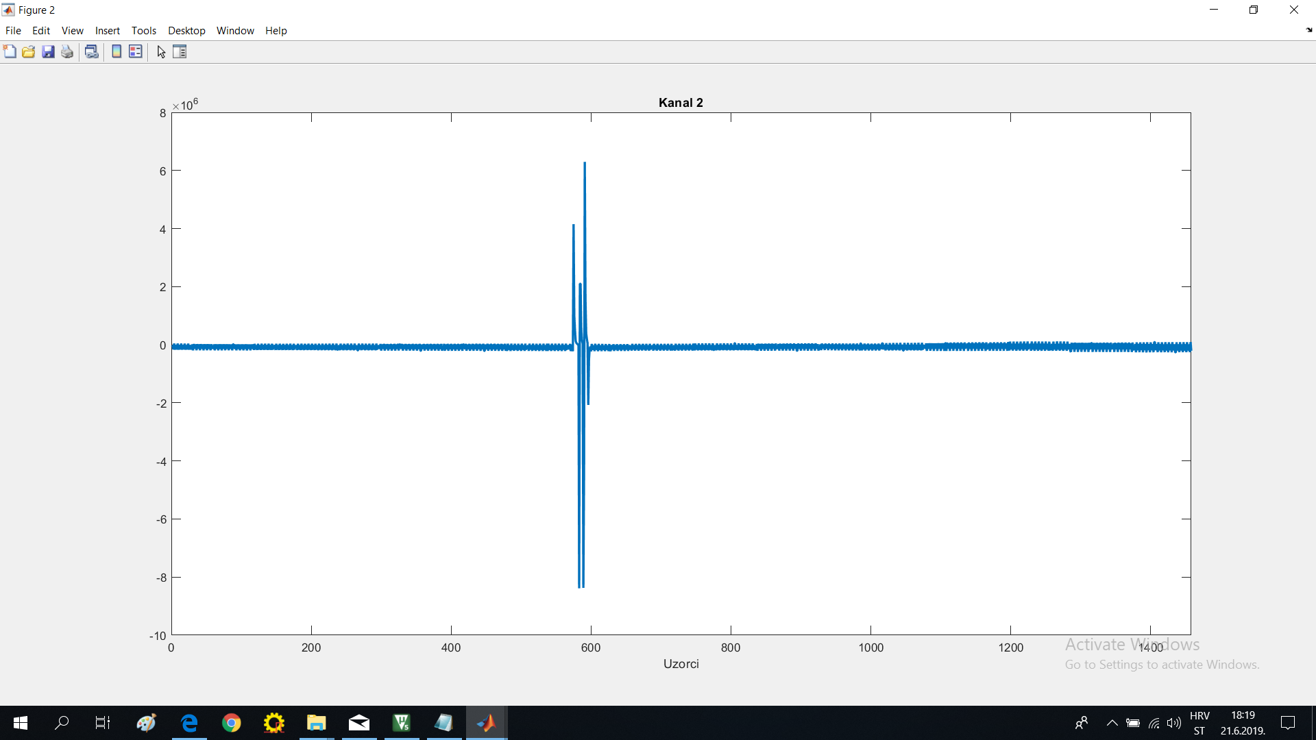
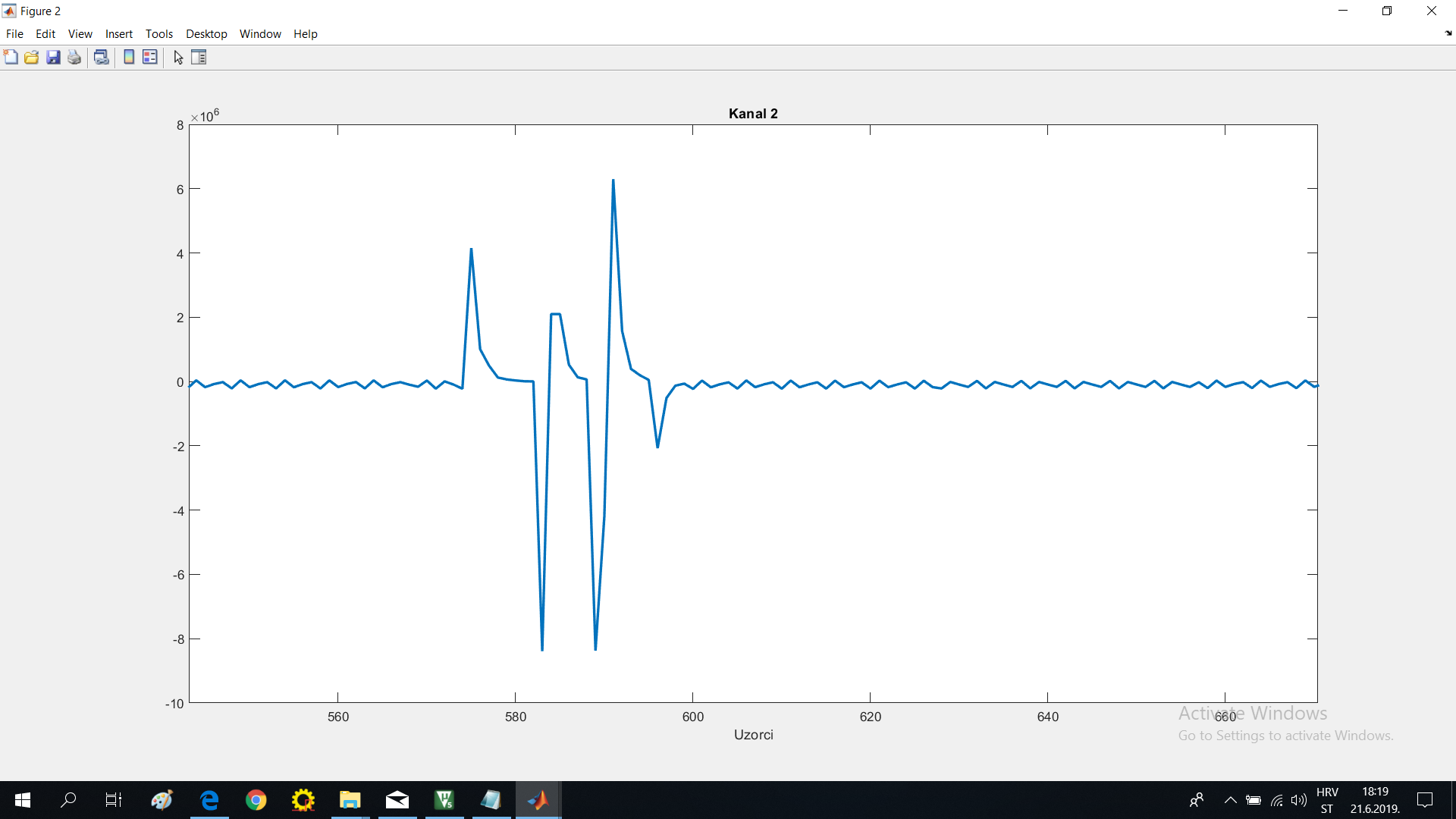
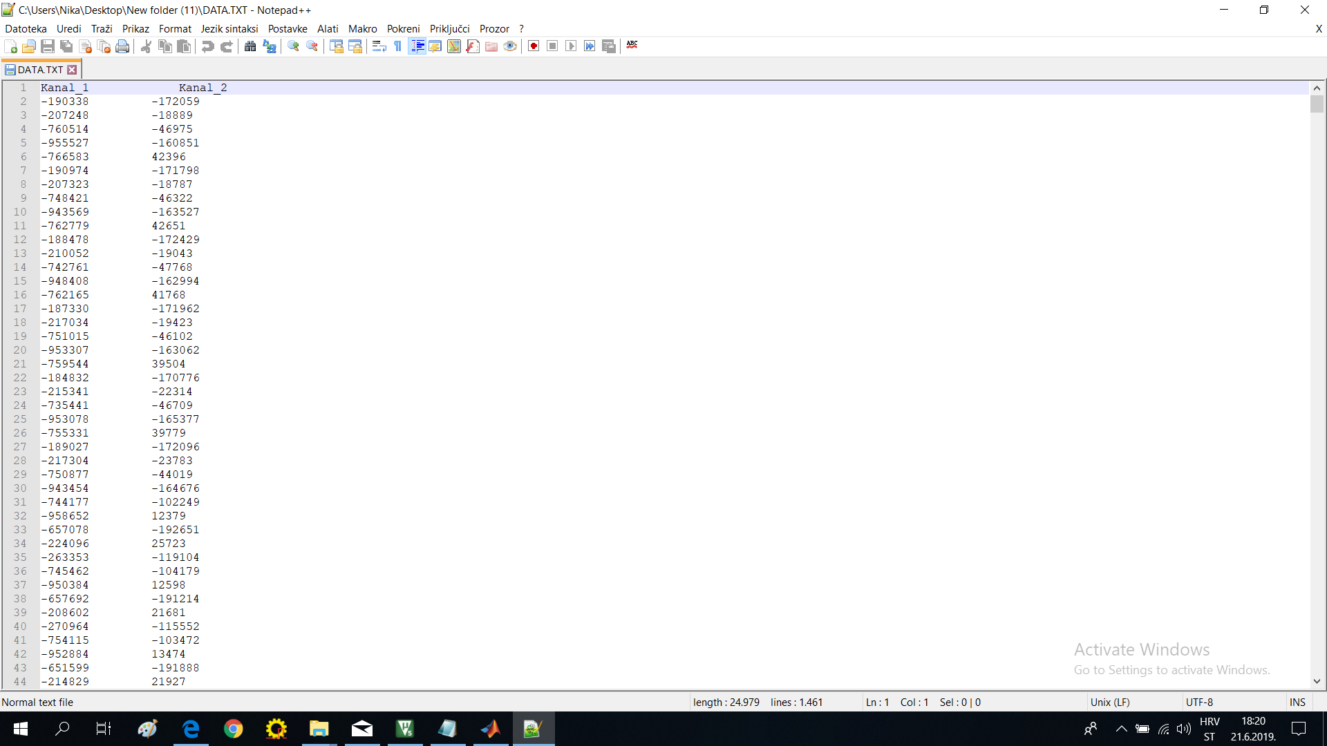
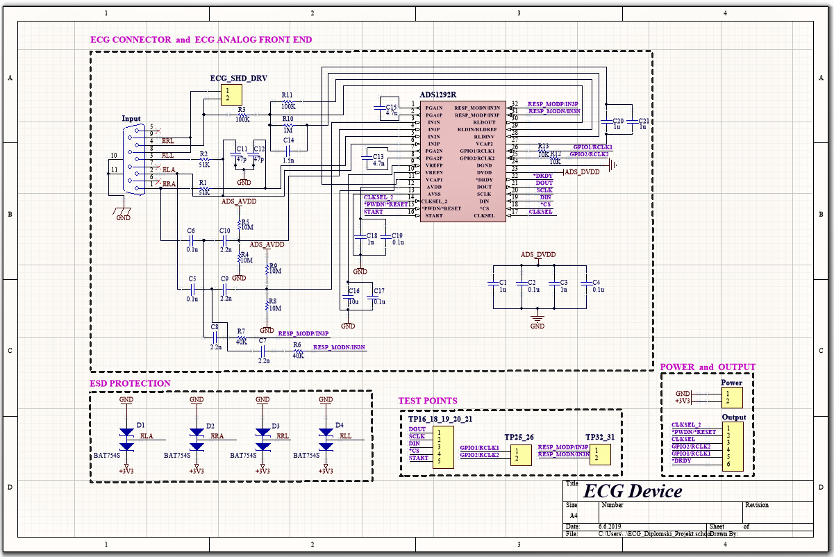
I have design a circuit similar to the one in the ads1292r EVM and I have already established and verified the SPI comunication (between STM32F407VG and ADS1292R) and the test signal is working. The system uses 3 electrodes (RA,LA,RL - www.ti.com/.../slau384a.pdf ; Figure 48. ECG Cable Drawing ) and the circuit is design to get ECG and Respiration . I am stuck in getting both signals.
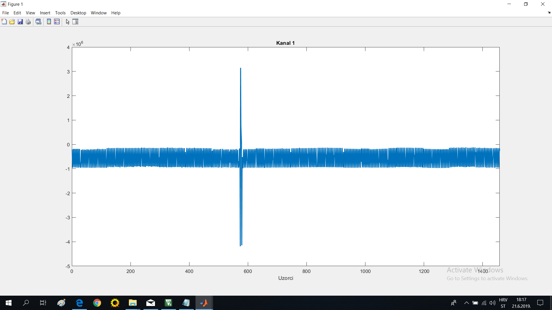
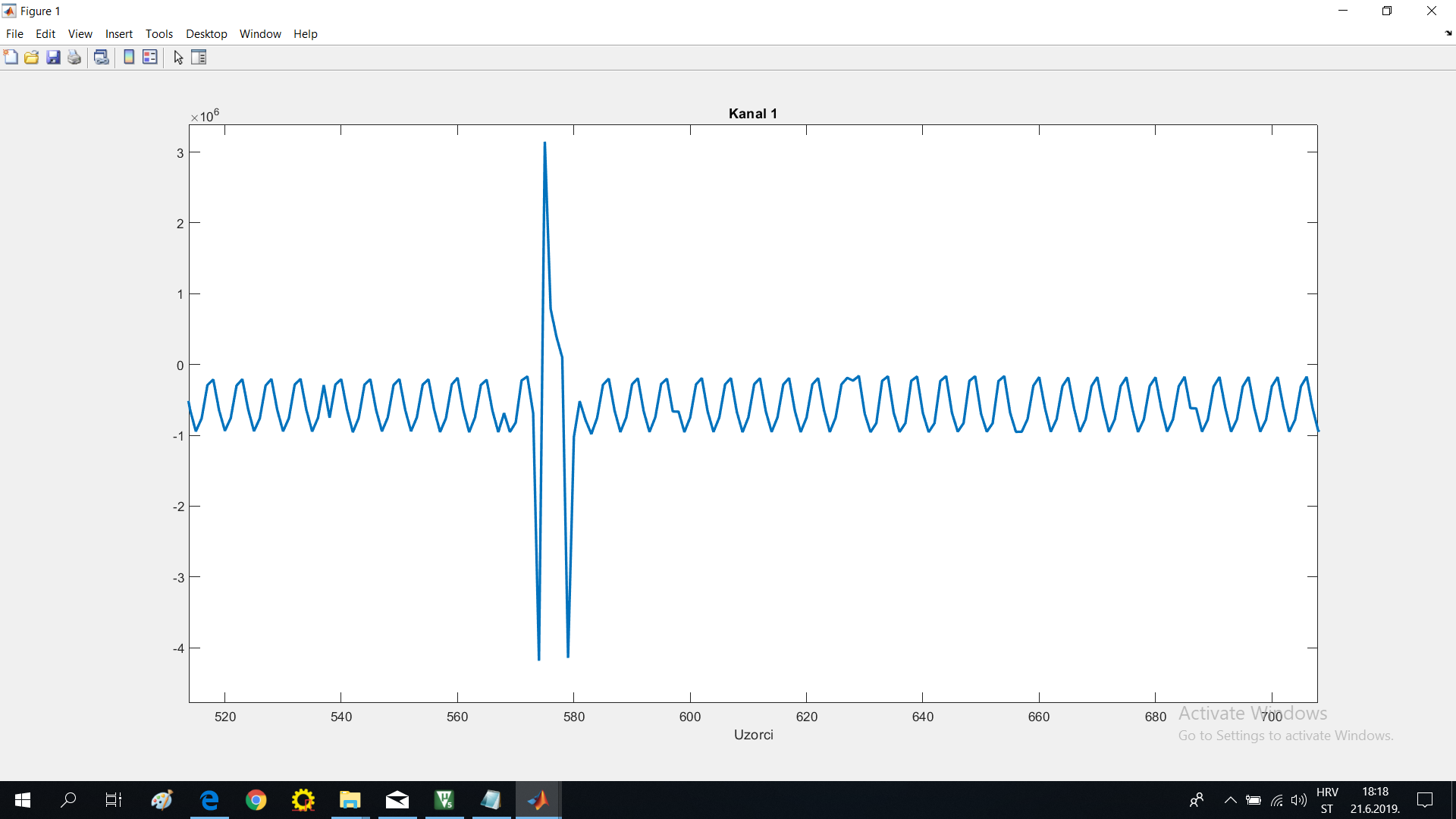
Respiration signal :

ECG signal :

Schematic:
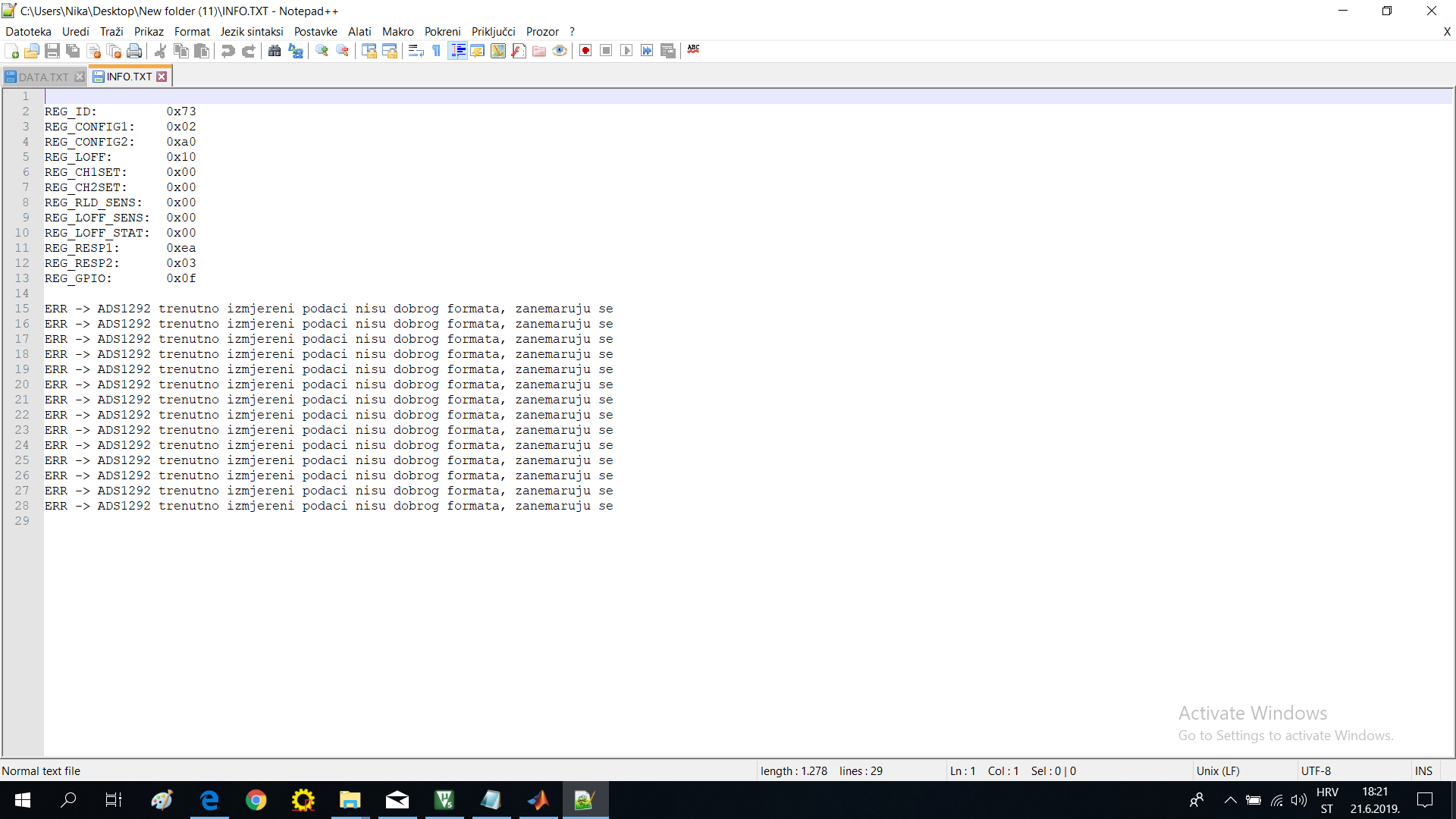
Initialization:
my_ADS1292_write_register(REG_CONFIG1, 0x02);
my_ADS1292_write_register(REG_CONFIG2, 0xA0);
my_ADS1292_write_register(REG_LOFF, 0x10);
my_ADS1292_write_register(REG_CH1SET, 0x09);
my_ADS1292_write_register(REG_CH2SET, 0x00);
my_ADS1292_write_register(REG_RLD_SENS, 0x00);
my_ADS1292_write_register(REG_LOFF_SENS, 0x00);
my_ADS1292_write_register(REG_LOFF_STAT, 0x14);
my_ADS1292_write_register(REG_RESP1, 0xEA);
my_ADS1292_write_register(REG_RESP2, 0x03);
my_ADS1292_write_register(REG_GPIO, 0x00);
Can you please help in solving problems?
Thank you,
N