This thread has been locked.

If you have a related question, please click the "Ask a related question" button in the top right corner. The newly created question will be automatically linked to this question.

ADS1118: ADS1118 ADC Mode Collection of K thermocouple

Part Number: ADS1118

Dear TI Engineer

  I use the stm32 microcontroller to drive the ADS1118 to collect K thermocouples.The collected data is incorrect.  Here's how I'm doing it,  See if there's a problem.Thanks

1、ADS1118 read and write function

uint16_t ADS1118_ReadConfReg(uint16_t reg)
{
    uint16_t conf_reg=0;
    
    SPI_CS_LOW;
    delay_us(100);
//    conf_reg = SPI_ReadData(Spi1_Obj,0x04FB);        //temprature sensor
    
    conf_reg = SPI_ReadData(Spi1_Obj,reg);    //ADC collect
//    conf_reg = SPI_ReadData(Spi1_Obj,0x89a);    //ADC collect
    SPI_CS_HIGH;
    
    return conf_reg;
}

uint32_t ADS1118_ReadWriteReg(void)
{
    uint32_t conf_reg=0;
    
    SPI_CS_LOW;
    delay_us(100);
    conf_reg = SPI_ReadData_32bit(Spi1_Obj,0x04EB04EB);
    
    SPI_CS_HIGH;
    
    return conf_reg;
}

2、main function processing

#define ReadADC_Reg                0x8283        //0x04e3

uint16_t ads1118_v=0;
uint32_t ads_reg = 0;
float ads_value = 0;

while(1)

{

ads1118_v = ADS1118_ReadConfReg(ReadADC_Reg);    //AD collect
ads_value = (float)ads1118_v *4.096/32768;

printf("ads118 value: %x ; ads1118_temprature: %.2f\r\n",ads1118_v,ads_value);

}

  • Dany,

    Instead of looking at the code, I think it's easier to look at the output data directly from the ADC. Report back with a set of 100 readings from the raw ADC data (not converted to temperature).

    When you say the collected data is incorrect, how is it incorrect? Is the data consistently incorrect, or are there bad reads occasionally? While this could be a problem in the converting the code to temperature, it could also be a problem with the method of collecting data, and not getting the data fast enough after a /DRDY indication.

    Joseph Wu

  • Dany,

    Just to make sure that you have this the ADS1118EVM is built like a thermocouple measurement application and you can find the user's guide here:

    There is also a short cookbook circuit here:

    Additionally you can find an application note on for this system here:

    There is also a TI Design here:

    Joseph Wu

  • Joseph Wu

       First of all,Thank you for your answer.

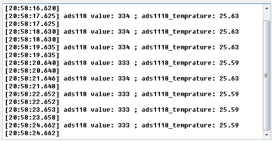
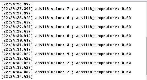
       In temprature sensor mode,the data is normal.  In ADC mode,the data is incorrect.  See  the screenshot below.

      1、This is ADC mode

        2、This is temprature mode

  • Dany,


    Right now, it looks like the internal temperature sensor measurement is working fine. If you're getting about 25.6°C, and the device is at room temperature, the reading should be fine. However, the ADC value is reading 0 or 1 for the measurement.

    This could be one of several things. First, you could be shorting the input voltage somewhere in the schematic. If you are running at the highest data rate, you might be seeing a little noise, with some offset. Second, you could be setting the wrong full-scale range for the ADC. Normally you would want to set the voltage to ±0.256V. For example, if you are in the ±4.096V FSR, the LSB for that range is 125uV. That is still small, but it would be easier to see deviations if you were in the ±0.256V FSR where the LSB is about 7.8uV.

    For the settings, I would also check a couple extra things. I would definitely use the device in single-shot conversion mode. When changing channels, Use this mode to make sure that I get the right reading for the right channel. I would also use a slower data rate to make sure the noise is not a big factor. You can look at the ADC settings for the thermocouple cookbook that I mentioned in my last post.

    After that, I think you should measure a real voltage source instead of a thermocouple just to test your system.

    If none of that helps to debug your system, then post your schematic. I'd like to see all of the connections to the ADS1118 and see what else is connected to the input.


    Joseph Wu

  • Joseph Wu

       Thank you for your patient response.

       Just now, I'll configure the full scale rang as your suggest. The data measured are as follows:

    #define ReadADC_Reg                0x8B8B

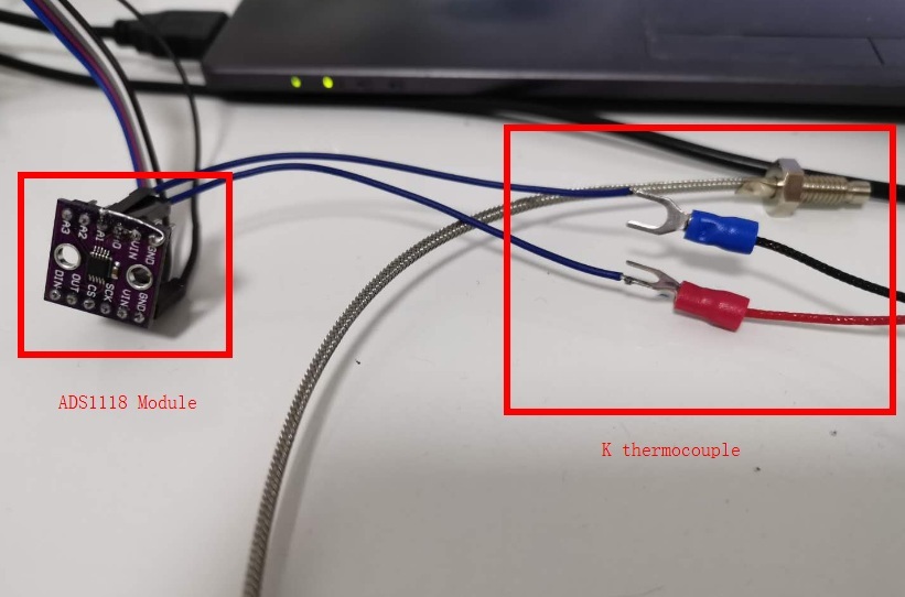
    Hardware connections :

  • Dany


    It seems to me that you're getting the correct data, but not reporting the temperture correctly. For calculating the temperature, you must first convert the cold-junction temperature to voltage with the following diagram.


    For the ADC, you get values for the thermocouple measurement of about 7. You do have some noise, which might be from EMI pickup from the wires in the system. If you do get 7 as an output code, and are using the ±0.256V FSR this converts to:

    7*7.8125uV = 54.68uV

    Then you use the internal temperature sensor and get the temperature. In your previous readings, you got 25.59°C (as an example).

    You then convert that temperature to a thermoelectric voltage through a k-type thermocouple table. This converts to 1.02415mV. Add this to the thermocouple voltage of 54.68uV. This becomes:

    1024.15uV+54.68uV = 1078.83uV.

    Convert this back to temperature and you get: 26.938°C.


    Joseph Wu

  • Joseph Wu

        Thank you for your analysis !

       I'll test it again based on your analysis.

       Have a nice day at work !