This thread has been locked.

If you have a related question, please click the "Ask a related question" button in the top right corner. The newly created question will be automatically linked to this question.

ADS1248: ADS1248

Part Number: ADS1248
Other Parts Discussed in Thread: ADS124S08

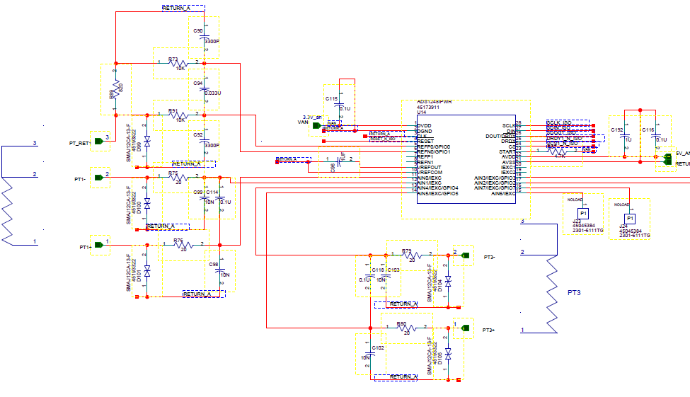
We use ADS1248 in the temperature measurement circuit of the PT100 sensors.

The measurement scheme is made with requirements of the datasheet and application mode recommendations.

In general, the circuit works correctly, but when the PT100 sensors are connected or disconnected from the circuit with the power supply turned on, the ADS1248 chip fails.

How to prevent this situation?


  • Hi Efim,

    Do you have any additional information you can provide?

    Is the IDAC current running through the PT100 sensor when the sensor is removed?

    Can you provide a schematic?

    What do you mean by the ADS1248 fails? Is the data corrupted? Is the chip locked up? 

    Are there any diodes on the inputs to prevent transients from reaching the device? 

  • Hi,

    When the sensor is removed, the IDAC current is not running.

    The ads1248 fails - the data is corrupted, and when i try to write to internal registers i dont get back the same data when i read.

    And the schematic is attached , please advice.

  • Hi Efim,

    Are you generating your reference voltage using the measurement across REFP/N0? 

    If an internal reference voltage is used, does the problem persist?

    When disconnecting/connecting the PT100, do you see a change in magnitude with respect to earth on your ground plane? 

  • Hi Alexander,

    1. We are generating reference voltage using the measurement across REFP

    2. We will check change in magnitude with respect to earth and we will let you know

    Best Regards.

  • Hi Alexander,

    When connector is disabled , in the inputs of pt+, and pt-, relative to analog ground we see voltage across 1v.

    See C114 capacitor in schematic.

    Probably, the capacitor has no route for discharging when the connector is removed. 

    The same problem when connector is connected, the voltage rise as needed but when we are moving to read from another channel the voltage arrives to 1v but no to zero.

    We tried to remove this capacitor and on this point the voltage arrived to 0 , but in the application of datasheet 

    this capacitor attend.

    Another question, can we plug or unplug the PT(connector) during the power is on and still the ADS1248 will work properly?

    Best Regards.

  • Hi Efim,

    Plugging and unplugging sensors in is typically not a problem if there's adequate input protection. Since the excitation current is being sourced through the analog inputs, this is probably where the issue is coming from. 

    The TVS diodes will pass 12V, and probably fully clamp around 16-17V. The 20ohm input resistance is too small to prevent the large current from entering the analog inputs. 12V - 5.3V drop accross the diode is 6.7V. Divided by the input resistance of 20ohm yields 335mA of current flowing into the analog inputs. The absolute maximum rating for the device is 10mA. 

    At this point, the device may be damaged. Instead of sourcing the current through the inputs, try using the unused pins to source the current, bypassing the input filters. Schottky diodes can be added to the excitation current lines to prevent large voltages from reaching the ADC. Additionally, larger resistors can be used for the analog input filter. 

    If you haven't seen it already, please take a look at A Basic Guide to RTD Measurements:

    http://www.ti.com/lit/an/sbaa275/sbaa275.pdf

    And this app note:

    http://www.ti.com/lit/an/sbaa201/sbaa201.pdf

     The 1V accross capacitor C114 is charged from the IDAC source. The purpose of this is that it should give a full-scale result as an indicator that a lead(s) is missing.

  • Hi Alex,

    We have already removed the TVSs from the board, they are only on the schematic - the voltage was measured without the TVSs.

    This didn't solve the problem - connect and disconnect the PT on power ON.   

    Regards.

  • Hi Efim,

    I did not mean from my previous post to remove the TVS diodes. They are necessary for adequate input protection. 

    I also mentioned routing the excitation current through IEXC1 and IEXC2, not the analog input pins. 

  • Hi Alexander,

    According to the Datasheet, component ADS1248 provide 8 Independently

    Selectable Inputs, from which I can build 3 independent measurement channels.

    Using the excitation current through IEXC1 and IEXC2 , allows you to build up to 2 measuring channels.


    So ,We would like to use this device for maximize cost effective by using it for measure 3 channels

    Please advice


    Best Regards


  • Hi Efim,

    I understand the reason for disconnecting and re-connecting PT100 sensors now. 

    I believe you have 2 options, modify your input protection scheme such that the input current is limited to less than +/-10mA, or try evaluating the ADS124S08 which has additional input channels. 

    This video series is still in the works, but has lots of information to get started on input protection: https://training.ti.com/eos-and-esd-adc?cu=1128375

    I'm hoping to complete the series by end of next week. The series focuses on SAR adc's, but most of the content is applicable to delta-sigmas as well. In short, you will have to increase the size of the filter resistor to limit the current as I pointed out in my previous post. 335mA is too much current for the device to handle.  

    The ADS124S08 is our latest and greatest device in this space. It incorporates all of the best features and has 12 configurable input channels. I encourage you to consider evaluating this device.