This thread has been locked.

If you have a related question, please click the "Ask a related question" button in the top right corner. The newly created question will be automatically linked to this question.

DDC114: Using Test signal to measure input bais current

Part Number: DDC114

Hi,

Is it possible to use the test signal from the DDC114 to be able to measure each channel input bias current?

My goal is to substract the DDC114 input bias current from the photodiode current to enable current measurement range below 10pA.

Thanks in advance.

Cyril.

  • Hi,

    I guess your idea is to disconnect the input internally (with the test mode) and measure the Ibias. Sure, that would be a way... The only thing I am thinking is that not all the circuits in the device get taken into account (the input ESDs are likely also disconnected but don't think they would contribute much, if anything).

    Best would be to keep it connected but simply have zero signal coming in so that you remove external leakage sources too, but I imagine that you are actually trying to avoid that hassle (you have no easy way to do that...).

    Will check with our design team to see what are the sources weighting the most in Ibias and get back...

    Regards,
    Edu

  • Hi Cyril,

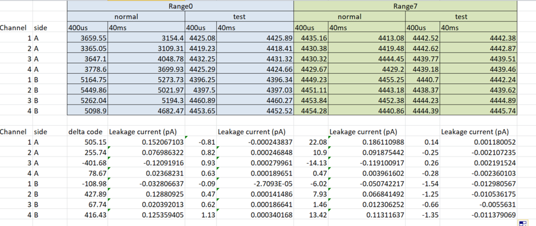
    It's been a while but I thought to send you some data we took recently, in case it can still be of any  help for you or someone else reading this... We took a DDC114 and ran several experiments:

    Not sure if it is clear or not but basically we use a short integration time (400us) and a long one (40ms), and subtract one from the other so to remove the initial offset and extract the leakage term. We did this in two range settings and with the test mode on/off (to disconnect the input). As the physical input was always disconnected (floating) the only thing we are disconnecting on that mode is the internal input protection diodes.

    As you can see, most of the leakage seems to actually come from those diodes and for the same reason, doesn't change with range. So, using the test mode will not allow you to measure the maximum contributor of leakage (because it disconnects it). Notice that the leakage measures different for each of the sides of the input (A or B). That is likely due to the fact that the leakage current comes as a result of the tiny input offset (bias) voltage across the ESDs, and the input offset is different for each of the two amplifiers.

    In either case, leakage looks very small although sure, I guess there could be outliers with larger one. I think one possibility may be to change the bias on your diode between several values to create few equations (using the diode transfer curve model)  and extract from there the different contributors, but I am not 100% this will work.

    This thread will likely close itself in few hours. If you need further discussion, I think the only way would be for you to post again a different thread.

    Best regards,
    Edu