This thread has been locked.

If you have a related question, please click the "Ask a related question" button in the top right corner. The newly created question will be automatically linked to this question.

ADS1220 is not sending proper data in continuous mode

Part Number: ADS1220

Sir

I am new to ADS1220.

In Single shot conversion it provide me good data that i want.When i switch to continous mode it will provide me random values.

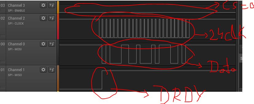
I dont understand how RDATA command in ADS1220 and also provide DRDY pin used to acess data in continous mode.

Here is the code:

#include "N76E003.h"
#include "SFR_Macro.h"
#include "Function_define.h"
#include "Common.h"
#include "Delay.h"

//typedef unsigned char uint8_t;
typedef signed long int32_t;
//typedef unsigned short uint16_t;
typedef signed short int16_t;
//typedef unsigned long uint32_t;
typedef signed char int8_t;

typedef float fp32_t;
typedef double fp64_t;

#define SS P15
#define MISO P01
#define MOSI P00
#define SCLK P10
#define DRDY P11

#define HIGH 1
#define LOW 0
#define CONFIG_REG0_ADDRESS 0x00
#define CONFIG_REG1_ADDRESS 0x01
#define CONFIG_REG2_ADDRESS 0x02
#define CONFIG_REG3_ADDRESS 0x03
#define WREG 0x40
#define RREG 0x20
#define SPI_MASTER_DUMMY 0xFF
#define RESET 0x06 //Send the RESET command (06h) to make sure the ADS1220 is properly reset after power-up
#define START 0x08 //Send the START/SYNC command (08h) to start converting in continuous conversion mode

//Config registers
#define CONFIG_REG0_ADDRESS 0x00
#define CONFIG_REG1_ADDRESS 0x01
#define CONFIG_REG2_ADDRESS 0x02
#define CONFIG_REG3_ADDRESS 0x03

#define REG_CONFIG1_DR_MASK 0xE0
#define REG_CONFIG0_PGA_GAIN_MASK 0x0E
#define REG_CONFIG0_MUX_MASK 0xF0

#define DR_20SPS 0x00
#define DR_45SPS 0x20
#define DR_90SPS 0x40
#define DR_175SPS 0x60
#define DR_330SPS 0x80
#define DR_600SPS 0xA0
#define DR_1000SPS 0xC0

#define PGA_GAIN_1 0x00
#define PGA_GAIN_2 0x02
#define PGA_GAIN_4 0x04
#define PGA_GAIN_8 0x06
#define PGA_GAIN_16 0x08
#define PGA_GAIN_32 0x0A
#define PGA_GAIN_64 0x0C
#define PGA_GAIN_128 0x0E

#define MUX_AIN0_AIN1 0x00
#define MUX_AIN0_AIN2 0x10
#define MUX_AIN0_AIN3 0x20
#define MUX_AIN1_AIN2 0x30
#define MUX_AIN1_AIN3 0x40
#define MUX_AIN2_AIN3 0x50
#define MUX_AIN1_AIN0 0x60
#define MUX_AIN3_AIN2 0x70
#define MUX_AIN0_AVSS 0x80
#define MUX_AIN1_AVSS 0x90
#define MUX_AIN2_AVSS 0xA0
#define MUX_AIN3_AVSS 0xB0

#define MUX_SE_CH0 0x80
#define MUX_SE_CH1 0x90
#define MUX_SE_CH2 0xA0
#define MUX_SE_CH3 0xB0

#define _BV(bit) (1<<(bit))

long value =0;unsigned char rd = 0;
int32_t mResult32 = 0;
unsigned char i =0,buf[3]=0,buf1[8];
void intialise_PIN(void);
void write_byte(unsigned char addr,unsigned char dat);
unsigned char read_byte(unsigned char addr);
void write(unsigned char addr);
unsigned char read(unsigned char ad);
void intialise_ADC(void);
long ADC_READ();
void SPI_Command(unsigned char data_in);

void intialise_ADC(void)
{
unsigned char rd = 0;
SPI_Command(RESET);
Timer0_Delay100us(300);

write_byte(CONFIG_REG0_ADDRESS,0x00);// Selection of MUX GAIN and PGA_Bypass
write_byte(CONFIG_REG1_ADDRESS,0x04);//Selection Continuos mode data
SPI_Command(START);
write_byte(CONFIG_REG2_ADDRESS,0x00);//FIR filter configuration
write_byte(CONFIG_REG3_ADDRESS,0x00); //DRDY PIn
//Timer0_Delay100us(100);

//rd = read_byte(CONFIG_REG0_ADDRESS);
// for(i=0;i<3;i++)
//
// {
// buf[i] = rd%10 + '0';
// rd = rd/10;
// }
// Send_Data_To_UART0 (buf[2]);
// Send_Data_To_UART0 (buf[1]);
// Send_Data_To_UART0 (buf[0]);
// Send_Data_To_UART0(0x0d);
//
//rd = read_byte(CONFIG_REG1_ADDRESS);
// for(i=0;i<3;i++)
//
// {
// buf[i] = rd%10 + '0';
// rd = rd/10;
// }
// Send_Data_To_UART0 (buf[2]);
// Send_Data_To_UART0 (buf[1]);
// Send_Data_To_UART0 (buf[0]);
// Send_Data_To_UART0(0x0d);
//rd = read_byte(CONFIG_REG2_ADDRESS);
// for(i=0;i<3;i++)
//
// {
// buf[i] = rd%10 + '0';
// rd = rd/10;
// }
// Send_Data_To_UART0 (buf[2]);
// Send_Data_To_UART0 (buf[1]);
// Send_Data_To_UART0 (buf[0]);
// Send_Data_To_UART0(0x0d);
//rd = read_byte(CONFIG_REG3_ADDRESS);
// for(i=0;i<3;i++)
//
// {
// buf[i] = rd%10 + '0';
// rd = rd/10;
// }
// Send_Data_To_UART0 (buf[2]);
// Send_Data_To_UART0 (buf[1]);
// Send_Data_To_UART0 (buf[0]);
// Send_Data_To_UART0(0x0d);
//
// Timer0_Delay100us(100);


}
void intialise_PIN(void)
{
P15_Quasi_Mode;// SS P15
P12_PushPull_Mode;
P00_Quasi_Mode;//MOSI P00
P10_Quasi_Mode;//SCLK
P01_Input_Mode;//MISO P01
//P01_PushPull_Mode;
P11_Input_Mode;//DRDY
InitialUART0_Timer3(4800);
SS = 1;

}

void write_byte(unsigned char addr,unsigned char dat)
{

SS = 0;
SCLK = 0;
Timer0_Delay100us(5);
//0 WREG =0;
write(WREG|(addr<<2));
write(dat);
Timer0_Delay100us(5);

SS = 1;
}
unsigned char read_byte(unsigned char addr)
{
uint8_t data1;

SS = 1; // Make sure we start with /CS high
SCLK = 0; // and CK low
Timer0_Delay100us(100);
write(RREG|(addr<<2));
data1 = read(addr);
Timer0_Delay100us(5); // and loop back
SS = 1;

return data1;
}

void write(unsigned char addr)
{

unsigned char SPICount; // Counter used to clock out the data

unsigned char SPIData;

SPIData = addr; // Preload the data to be sent with Address

for (SPICount = 0; SPICount < 8; SPICount++) // Prepare to clock out the Address byte
{
if (SPIData & 0x80) // Check for a 1
MOSI = 1; // and set the MOSI line appropriately
else
MOSI = 0;
SCLK = 1; // Toggle the clock line
SCLK = 0;
SPIData <<= 1; // Rotate to get the next bit

}

MOSI = 0;

}


unsigned char read(unsigned char ad)
{
unsigned char SPICount; // Counter used to clock out the data

unsigned char SPIData;

SPIData = 0;
for (SPICount = 0; SPICount < 8; SPICount++) // Prepare to clock in the data to be fread
{
SPIData <<=1; // Rotate the data
SCLK = 1; // Raise the clock to clock the data out of the MAX7456
SPIData = SPIData|MISO; // Read the data bit
// Timer0_Delay100us(2);
SCLK = 0; // Drop the clock ready for th enext bit
}
return SPIData;

}

long ADC_READ()
{
static unsigned char SPI_Buff[3],i;
int32_t mResult32 = 0;
long int bit24;

// SPI_Command(START);

if(DRDY == 0 )
{
SS = 0;
SCLK = 0;
Timer0_Delay100us(100);
for(i = 0; i < 3 ;i++)
{

SPI_Buff[i] = read(SPI_MASTER_DUMMY);

}
Timer0_Delay100us(100);
SS = 1;
bit24 = SPI_Buff[0];
bit24 = (bit24 << 8)|SPI_Buff[1];
bit24 = (bit24 << 8)|SPI_Buff[2];

bit24 = (bit24 << 8);
mResult32 = bit24;

}
return mResult32;


}


void SPI_Command(unsigned char data_in)
{
SS = 0;
Timer0_Delay100us(2);
SS = 1;
Timer0_Delay100us(2);
SS = 0;
Timer0_Delay100us(2);
write(data_in);
Timer0_Delay100us(2);
SS = 1;
}

void main()
{

bit RDY_old = 0,RDY_new = 0;unsigned char i;
long ADCResult =0;
long int bit24 = 0;
intialise_PIN();
intialise_ADC();
//SPI_Command(START);
P12=1;
while(1)
{


//SPI_Command(START);
//Timer1_Delay10ms(10);

RDY_old = RDY_new;//
RDY_new = DRDY;//

if(RDY_old == 1 && RDY_new == 0 )
{
P12=~P12;
SS = 0;
for ( i = 0; i < 24; i++)//To acess 24 bit data
{

SCLK = 0;
ADCResult = ADCResult << 1 | MISO;
SCLK = 1;
Timer0_Delay100us(5);
}

SS =1;

if((ADCResult&0x800000)==0x800000)
{
ADCResult = (0xffffff - ADCResult);
// Send_Data_To_UART0 (aa[1]);
}
else
{

ADCResult = ADCResult;

}

bit24 = ADCResult;
for(i=0;i<7;i++)

{
buf[i] = bit24%10 + '0';
bit24 = bit24/10;
}
//SPI_Command(RESET);
// Timer0_Delay100us(300);

// Send_Data_To_UART0 (buf[7]);
Send_Data_To_UART0 (buf[6]);
Send_Data_To_UART0 (buf[5]);
Send_Data_To_UART0(buf[4]);
Send_Data_To_UART0 (buf[3]);
Send_Data_To_UART0(buf[2]);
Send_Data_To_UART0(buf[1]);
Send_Data_To_UART0(buf[0]);
Send_Data_To_UART0(0x0d);
//write_byte(CONFIG_REG1_ADDRESS,0x00);


// SPI_Command(START);


}

}


}

ALso picture conitnous data:

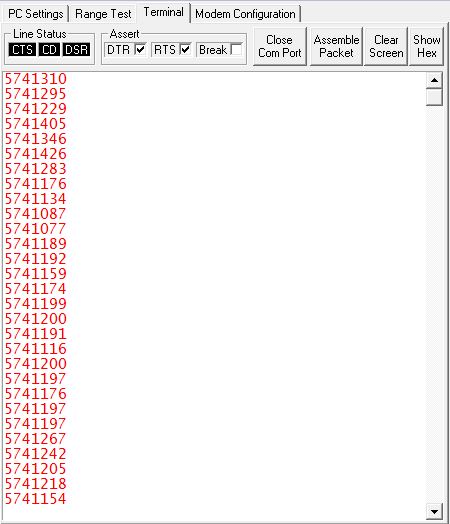
Here is Data look like continous mode:

Here image of single shot mode .is it possible to make single shot mode to continuous mode using START cmd again and again.

Please Help out this problem as soon as possible,

Please me out understand this problem

Pranav 

Designinnova

  • Hello Poster!

    Our support staff is taking time with their families for the Independence Day holiday here in the US.  It may be July 8th before we can get back to you with help on your query.  We apologize in advance for the delay and will get back to you as soon as possible.

  • Hi Pranav,

    It appears you are bit-banging the GPIO port to communicate with the ADS1220.  When running in continuous mode you either have to read the data out completely between conversions or you need to use the RDATA command.  The advantage of the RDATA command is that the output buffer will not be automatically updated when a new conversion completes.

    I suspect that you are getting data corruption in continuous mode because you are reading the data and a new conversion completes in the middle of your read of results.  If you attach your Saleae file of the continuous mode I can verify if that is the case.

    The way your code is structured it may be best and easiest to run in single-shot mode.  As soon as the data are read you can issue another start.  In that way can can control when you read from the device and when you start a conversion.

    Best regards,

    Bob B

  • Hi Pranav,

    I see that you rejected my answer, so perhaps I need more information and specific details regarding what you are attempting to accomplish.  If you wish to run in continuous mode, you must either read the data results directly and completely before the next DRDY transition to capture every conversion.  If you are not able to do so, then you must issue the RDATA command or you risk having corrupted data.

    There is example code using a micro with an SPI peripheral that can be downloaded.

    http://www.ti.com/lit/zip/SBAC227

    Best regards,

    Bob B

  • Actually made whole new code

    It is giving value in single shot mode(When i press reset button in microcontroller) .when i CM =1 than it also working in single shot mode further also i providing START command too.Why it is working single shot mode(When i press reset button in microcontroller).

    Here is code:

    #include "N76E003.h"
    #include "SFR_Macro.h"
    #include "Function_define.h"
    #include "Common.h"
    #include "Delay.h"

    //typedef unsigned char uint8_t;
    typedef signed long int32_t;
    //typedef unsigned short uint16_t;
    typedef signed short int16_t;
    //typedef unsigned long uint32_t;
    typedef signed char int8_t;

    typedef float fp32_t;
    typedef double fp64_t;

    #define SS P15
    #define MISO P01
    #define MOSI P00
    #define SCLK P10
    #define DRDY P11

    #define HIGH 1
    #define LOW 0
    #define CONFIG_REG0_ADDRESS 0x00
    #define CONFIG_REG1_ADDRESS 0x01
    #define CONFIG_REG2_ADDRESS 0x02
    #define CONFIG_REG3_ADDRESS 0x03
    #define WREG 0x40
    #define RREG 0x20

    #define RESET 0x06 //Send the RESET command (06h) to make sure the ADS1220 is properly reset after power-up
    #define START 0x08 //Send the START/SYNC command (08h) to start converting in continuous conversion mode
    #define POWERDOWN 0x02
    unsigned char rd = 0;
    bit RDY_old = 0,RDY_new = 0;unsigned char i;
    long bit24 = 0;
    unsigned char i =0,buf[8]=0,buf1[3]=0;

    void intialise_PIN(void);
    void write(unsigned char dat);
    void write_byte(unsigned char addr,unsigned char dat);
    unsigned char read();
    unsigned char read_byte(unsigned addr);
    void intialise_ADC(void);
    void SPI_Command(unsigned char data_in);
    long ADC_read_SingleShotMode();
    long ADC_read_ContinuousShotMode();


    void write(unsigned char dat)
    {
    unsigned char SPICount;
    unsigned char SPIdata;
    //SCLK = 0;
    SPIdata = dat;

    for(SPICount =0;SPICount<8;SPICount++)
    {
    if((SPIdata & 0x80)== 0x80)
    MOSI = 1;
    else
    MOSI = 0;
    Timer0_Delay100us(2);
    SCLK = 1;
    Timer0_Delay100us(3);
    SCLK = 0;
    Timer0_Delay100us(2);
    SPIdata <<= 1;
    }
    MOSI = 0;

    }

    void write_byte(unsigned char addr,unsigned char dat)
    {

    SS = 0;
    Timer0_Delay100us(5);
    write(WREG|addr>>2);
    write(dat);
    Timer0_Delay100us(5);
    SS = 1;

    }

    unsigned char read()
    {
    unsigned char SPICount;
    unsigned char SPIdata;
    SCLK = 0;
    Timer0_Delay100us(3);
    for(SPICount =0;SPICount<8;SPICount++)
    {
    SCLK = 1;
    Timer0_Delay100us(3);
    SPIdata = SPIdata<<1|MISO ;
    Timer0_Delay100us(2);
    SCLK = 0;
    Timer0_Delay100us(2);
    }
    SCLK = 0;
    return SPIdata;
    }

    unsigned char read_byte(unsigned addr)
    {
    unsigned char dat = 0;
    SS = 0;
    Timer0_Delay100us(5);
    write(RREG|addr>>2);
    dat = read();
    Timer0_Delay100us(5);
    SS = 1;
    return dat;
    }

    long ADC_read_SingleShotMode()
    {
    static ADC_Result[3] = 0;
    //SPI_Command(START);
    Timer0_Delay100us(10);

    if(DRDY == 0)
    {
    SS = 0;
    //
    Timer0_Delay100us(0.50);
    for(i = 0;i<3;i++)
    {
    ADC_Result[i] = read();
    }
    Timer0_Delay100us(0.25);
    SS = 1;

    bit24 = ((int32_t)ADC_Result[0]<<16);
    bit24 = ((int32_t)ADC_Result[1]<<8)|bit24;
    bit24 = ADC_Result[2]|bit24;

    if((bit24& 0x800000)==0x800000)
    {

    bit24 = (0xffffff - bit24);
    buf[7]='-';

    }
    else
    {
    bit24 = bit24;
    buf[7]='+';
    }
    // bit24 = bit24>>8;
    for(i=0;i<7;i++)

    {
    buf[i] = bit24%10 + '0';
    bit24 = bit24/10;
    }
    Send_Data_To_UART0(buf[7]);
    Send_Data_To_UART0(buf[6]);
    Send_Data_To_UART0(buf[5]);
    Send_Data_To_UART0(buf[4]);
    Send_Data_To_UART0(buf[3]);
    Send_Data_To_UART0(buf[2]);
    Send_Data_To_UART0(buf[1]);
    Send_Data_To_UART0(buf[0]);
    Send_Data_To_UART0(0x0d);

    }
    return bit24;

    }

    void intialise_ADC(void)
    {

    unsigned char rd = 0;
    Timer0_Delay100us(50);
    SS = 1;
    SPI_Command(RESET);
    Timer0_Delay100us(300);

    write_byte(CONFIG_REG0_ADDRESS,0x00);// Selection of MUX GAIN and PGA_Bypass
    write_byte(CONFIG_REG1_ADDRESS,0x04);//Selection Continuos mode data
    SPI_Command(START);
    write_byte(CONFIG_REG2_ADDRESS,0x40);
    //FIR filter configuration
    write_byte(CONFIG_REG3_ADDRESS,0x00); //DRDY PIn


    SS = 0;
    }

    void intialise_PIN(void)
    {
    P15_Quasi_Mode;// SS P15
    P12_PushPull_Mode;
    P00_Quasi_Mode;//MOSI P00
    P10_Quasi_Mode;//SCLK
    P01_Input_Mode;//MISO P01
    //P01_PushPull_Mode;
    P11_Input_Mode;//DRDY
    InitialUART0_Timer3(4800);
    SS = 1;
    SCLK = 1;
    }

    void SPI_Command(unsigned char data_in)
    {
    //SS = 0;
    //Timer0_Delay100us(2);
    //SS = 1;
    //Timer0_Delay100us(2);
    SS = 0;
    Timer0_Delay100us(2);
    write(data_in);
    Timer0_Delay100us(2);
    SS = 1;
    }
    long ADC_read_ContinuousShotMode()
    {
    static ADC_Result[3] = 0;
    //SPI_Command(START);
    Timer0_Delay100us(10);

    if(DRDY == 0)
    {
    SS = 0;
    //
    //Timer0_Delay100us(50);
    for(i = 0;i<3;i++)
    {
    ADC_Result[i] = read();
    }
    // Timer0_Delay100us(50);
    SS = 1;

    bit24 = ((int32_t)ADC_Result[0]<<16);
    bit24 = ((int32_t)ADC_Result[1]<<8)|bit24;
    bit24 = ADC_Result[2]|bit24;

    if((bit24& 0x800000)==0x800000)
    {

    bit24 = (0xffffff - bit24);
    buf[7]='-';

    }
    else
    {
    bit24 = bit24;
    buf[7]='+';
    }
    // bit24 = bit24>>8;
    for(i=0;i<7;i++)

    {
    buf[i] = bit24%10 + '0';
    bit24 = bit24/10;
    }
    Send_Data_To_UART0(buf[7]);
    Send_Data_To_UART0(buf[6]);
    Send_Data_To_UART0(buf[5]);
    Send_Data_To_UART0(buf[4]);
    Send_Data_To_UART0(buf[3]);
    Send_Data_To_UART0(buf[2]);
    Send_Data_To_UART0(buf[1]);
    Send_Data_To_UART0(buf[0]);
    Send_Data_To_UART0(0x0d);

    }
    return bit24;
    }
    void main()
    {

    intialise_PIN();
    intialise_ADC();
    //SPI_Command(START);
    P12_PushPull_Mode;
    while(1)
    {
    ADC_read_SingleShotMode();
    //Timer0_Delay100us(50);
    //SPI_Command(POWERDOWN);
    // Timer0_Delay100us(50);
    // intialise_ADC();
    }


    }


    Is single shot mode can be worked without reset provided by microcontroller?

    Also Let me know how to use RDATA command


  • Hi Pranav,

    One of the difficulties in writing code is having just enough code written to verify what you have is working as opposed to writing a complete program and then trying to find which code segments are not working.  So let's go through a couple of key segments and discuss them.

    void main()
    {
    
    intialise_PIN();
    intialise_ADC();
    //SPI_Command(START);
    P12_PushPull_Mode;
    while(1)
    {
    ADC_read_SingleShotMode();
    //Timer0_Delay100us(50);
    //SPI_Command(POWERDOWN);
    // Timer0_Delay100us(50);
    // intialise_ADC();
    }
    
    
    }

    Within the main function, you initialize (intialise_PIN()) the communication and assign the micro pins to the desired functionality. 

    The next thing you do is initialize the ADS1220 ( intialise_ADC()).  Within this function you issue a RESET command, delay until the command completes, and then write register settings (to register 0 and register 1.  The register settings include setting the ADS1220 to continuous mode.  You then issue the START command to start the ADS1220 converting in continuous conversion mode.  You then write to the register 2 (which will restart the conversion) and then to register 3 (which will again restart the conversion as stated in section 8.4.2.2 of the ADS1220 datasheet.)  Register 2 is set to 0x40 which uses an external reference as the conversion reference connected to the REFP0 and REFN0 inputs.

    The next call set the P12 pin to push-pull mode.  It is not clear what connects to this pin.

    The main function then goes into a continuous loop calling ADC_read_SingleShotMode(), even though the device is in continuous mode.

    void intialise_ADC(void)
    {
    
    unsigned char rd = 0;
    Timer0_Delay100us(50);
    SS = 1;
    SPI_Command(RESET);
    Timer0_Delay100us(300);
    
    write_byte(CONFIG_REG0_ADDRESS,0x00);// Selection of MUX GAIN and PGA_Bypass
    write_byte(CONFIG_REG1_ADDRESS,0x04);//Selection Continuos mode data
    SPI_Command(START);
    write_byte(CONFIG_REG2_ADDRESS,0x40);
    //FIR filter configuration
    write_byte(CONFIG_REG3_ADDRESS,0x00); //DRDY PIn


    SS = 0;
    }

    In the above function you communicate to the ADS1220 using functions SPI_Command() and write_byte().  Note that the CS pin of the ADS1220 must be low throughout an entire communication transaction.  Note also that at the beginning of the function shown above that the SS pin (connected to CS of the ADS1220) is set high at the beginning of the function and low at the end.  This should be the opposite.  However, this becomes redundant in your code and can be taken out.

    For example, the SPI_Command() function sets the SS low at the start of the function and returns high at the end of the function.  The SPI_Command calls the write() function which appears to be correct.  However, the communication should be verified with an oscilloscope or logic analyzer.

    The write_byte function takes two arguments with the first the device register address and the second the data.

    void write_byte(unsigned char addr,unsigned char dat)
    {
    
    SS = 0;
    Timer0_Delay100us(5); 
    write(WREG|addr>>2);
    write(dat);
    Timer0_Delay100us(5); 
    SS = 1;
    
    }

    Here again you are correctly setting the SS pin low at the beginning and high at the end of the function.  Also, this function writes two bytes to the ADS1220.  The first byte is supposed to be the WREG command and the address, and the second byte is the data.  The WREG command is 0x40 with the lower nibble containing the register to start writing as well as the number of registers to be written in one sequence (rrnn).  The way you have structured your code is to write one byte at a time, which is fine.  The problem is with the shifting of the register address.  The way you have structured the code is right-shift the contents by 2 (>>2).  This should actually be a left-shift <<2).  When you right-shift by 2, you will always be writing to the register 0 register.  So what you end up with is your last register write in the initialization of the ADC is to set the register 0 to 0, which is the default setting (actually all the register settings are at default settings).

    In the main function while loop you are continually calling the ADC_read_SingleShotMode() function.  As you have only issued the START command one time, you will only get one conversion result as you are still in single-shot mode due to the improper register write.

    To use the RDATA command, it is very similar to reading the data directly except you write the command first.

    write(0x10);
    for(i = 0;i<3;i++)
    {
    ADC_Result[i] = read();
    }

    Best regards,

    Bob B