This thread has been locked.

If you have a related question, please click the "Ask a related question" button in the top right corner. The newly created question will be automatically linked to this question.

AFE5809EVM: AFE5809evm + TSW1400evm proper functionality

Part Number: AFE5809EVM
Other Parts Discussed in Thread: AFE5809

Hi Ti,

Few days ago, I started to do my test, I am working in a SONAR project, basically, emitting a pulse train via FPGA, and the echo receiving via AFE5809evm and deserialize via TSW1400evm, I do not have a switch between my receptors and the AFE, only a period of time between emissions. I will show you some screens shots about my configurations inside the AFE gui and the TSW. Finally it is very important to remind that I am working with sensors 40 KHz, and I changed all the specific capacitor to work with low frequencies (1uF)

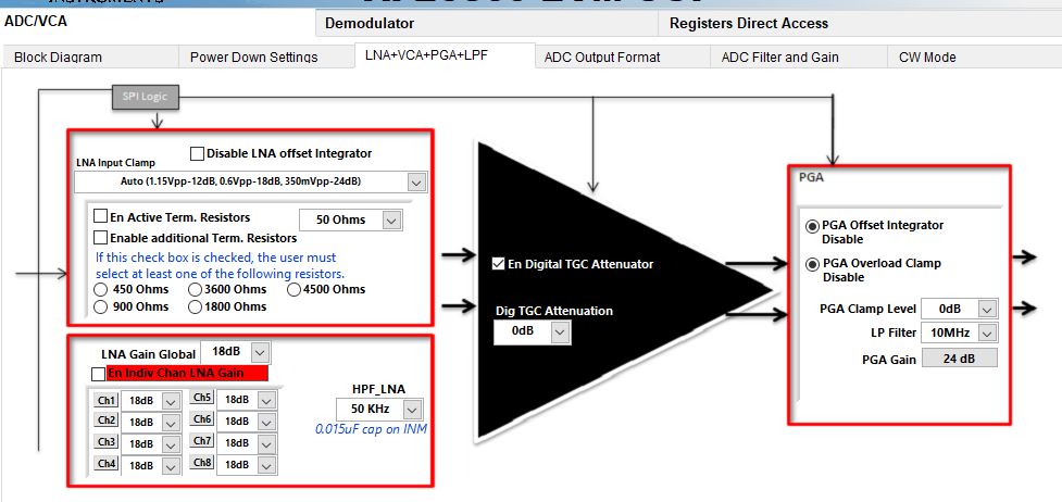
First image, check En digital TGC Attenuator, PGA offset integrator disabe, PGA overload clam disable, HPF_LNA 50 KHz, LNA gain global 18 dB

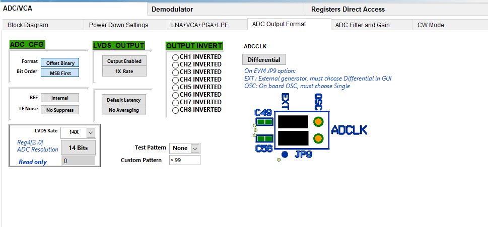
Second image, on the ADC output format only change the Format = offset binary and the bit order  MSB first


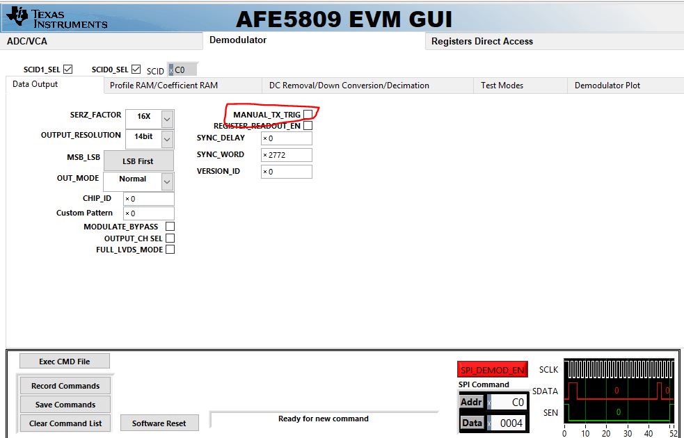
Thrid image, on the demodulator specifically in the DC removal/down conversion/decimation block, i tried checkin DC_removal_bypass, DWN_cnv_bypass, DEC_bypass.

Last image, TSW1400evm configs, as you can see, on the tab of data capture options I put continous capture.

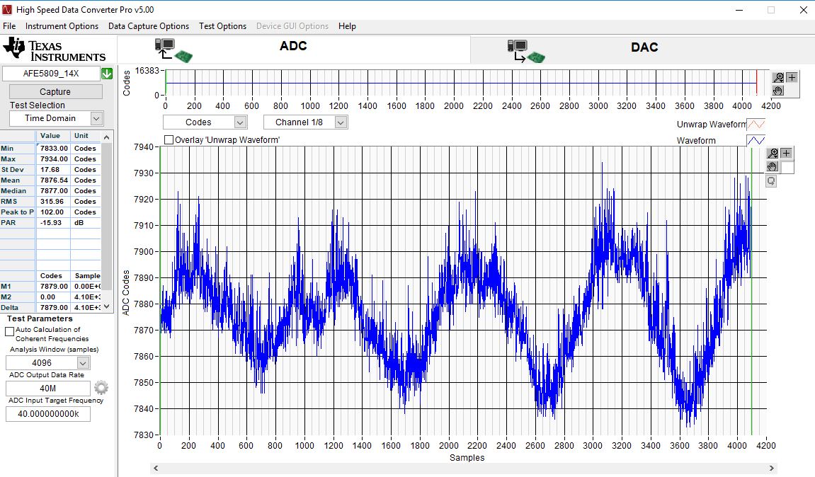
Finally, and apologizing beforehand, please help me if I am correct with my settings or what I did wrong, as you can see when making the continuous capture I am receiving a lot of noise, unwanted signals and I can not perceive or see the pulses of echo that should see.

Regards,

Mateo

macurecalde90@gmail.com

  • This noise is very low. Vpp is only 80 ADC LSBs, 80/16000 is very very small. you have some low freq noise due to connection or something. 

    please check with scope on the AFe input for pulse. Then you will need to use TX_TRIG to sync the capture.  

    Thanks!

  •  + Thank you very much for the clarification, for what you gave me to understand is that the other configurations are all good.
     + When referring to check the entry of the AFE you refer for example to TP1?
      + Now that you mentioned the use of the TX_TRIG to synchronize both evaluation modules, is this trigger configured only in the AFE5809evm? I have also read in section 8.6.2 Digital demodulator register description that the MANUAL_TX_TRIG must be checked for this event to occur. I attached a screenshot of the gui where it should be checked, but a problem occurs is that not marked this option.

    I really appreciate your help,

    Mateo

  • based on your configuraiton, you haven't entered the demod mode. you just use the ADC now. 

    So you can use the TSW1400 to generate the Trig signal for TX_TRIG input at AFE5809 EVM. please refer to the user manual for TSW1400 configruaiton in the Trig mode. 

    i mean to measure the INP signal, or at the SMA of input ch. 

    Thanks!

  • ok, I am still reading and understanding all the requirement about all settings, sorry for my mistakes, 

    please could you be more specific on I haven't entered the demod mode,

    For the second point I read in the High speed data converter pro GUI, page 16, about triggering operation, basically, I must connect  for example SYNC1(j11) form TSW to TX_SYNC_IN(j11) after checking the first and the second box on the Trigger option window.

    and again, thanks for helping me!

  • hope your issue is solved after revewing the AFE and TSW user manuals. Extra data manipulation steps need for Demod operation to generate I/Q data streams

    we will close the post. 

    Thanks!

  • first of all. it is not quite easy for others to locate your setting problem based on these pictures you gave, because there are too many setting options on the GUI.

    the demod stage CAN be deactivated on the GUI, I guess it is the "en demod after enter demod tap".

    your signal frequency and your settings can both result in a capturing failure for u, so I suggest you to check the problem source one by one. First you can test your settings by feeding a 500kHz signal. deactive the demod stage, and see if you can get reasonable results.

    after that, you can enable the demod stage, but, you check the Modulate_Bypass, DC REMOVEAL, DOWN CONV,DECIMATION BYPASS option, and test the OUTPUT CHANNEL SELECT option, to see if you can get right results that is the same with the datasheet.

    then you can test DOWN_CONV_bypass and DECIMATION BYPASS options

    after you have passed all these tests ,i guess you can have a good understanding about these settins, then you can do the M=4 I/Q test.

    one thing you have to check is the downconv frequency in the M=4 mode, 

    地址

    内容(HEX

    含义

    C3  

    6800

    SERZ_FACTOR: 16bit; OUTPUT RES: 16bit

    C4  

    10

    MSB first

    CA 

    1413

    MODULATE_BYPASS = 0;DEC_SHIFT_SCALE = 0 no additional delay; DHFP = 1, fcs = 450k ;OUTPUT_CHANNEL_SEL =0 no channel swap;FULL_LVDS_MODE = 0 use only LVDS1 3 5 7; SIN_COS_RESET_ON_TX_TRG = 1 continuous sine; Decimation and DOWN_CONV enabled, DC_REMOVE disabled

    DF  

    8044

    M and coefs are defined by register, and M = 4

    E0  

    1

    down cov sine frequency is defined by register

    E1  

    4000

    f = fs/4

    CE  

    0


    C0  

    4

    Generate internal TX_TRIG

    if your input frequency is 40k, and DHFP = 1, fcs = 450k , then all your signal will be filtered out.

    after you have passed the M=4 teset mode, then you can change your signal to 40kHz, AND MAKE SOME MODIFICATIONS TO THE .TXT FILE, and see what you get.