This thread has been locked.

If you have a related question, please click the "Ask a related question" button in the top right corner. The newly created question will be automatically linked to this question.

ADS127L01: ADS127L01 difference between acquisitions

Part Number: ADS127L01

Hi,

I'm experiencing a problem with these ADS127L01.

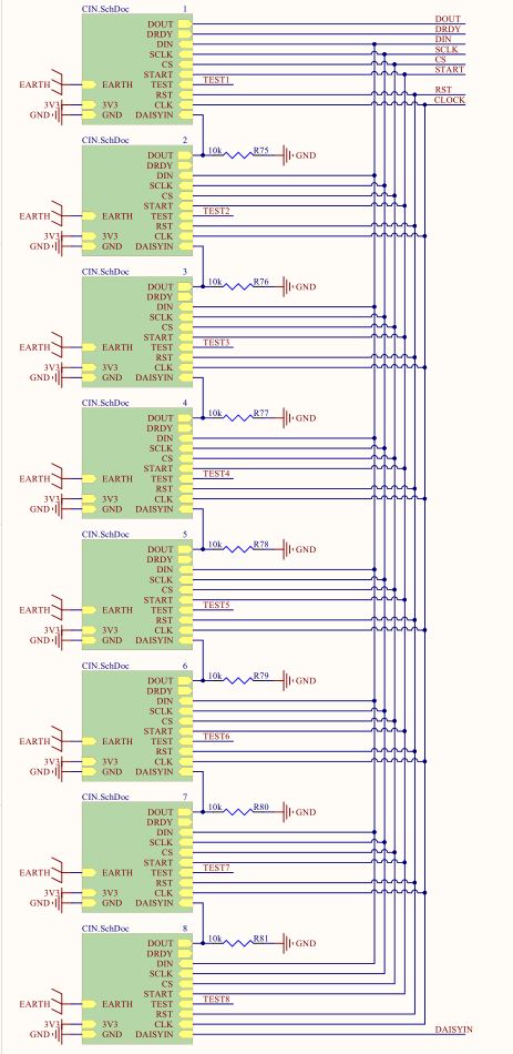
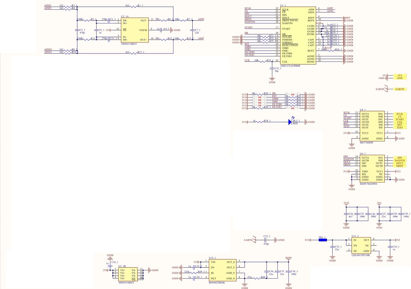
I have 8 adc connected in spi daisy chain, each one isolated from the others, with the same exact circuit and pcb

layout.

Master clock 256khz, 8kssp acquisition.


Running an acquisition for example on the first 2 channels with 0.5857V (measured directly on the adc inputs pin

with a 40000count multimeters)  I obtain two different results:

ch1....0x1DDE11

ch2....0x1E2F05


Reference voltage measure exactly the same 2.4996V.

CRC calculation seem to be ok.


I tried also phisically connect togheter the input of the two adc and connect them to same reference but the

difference between acquisitions remain the same.

Registers of the adc are all at their default state.


The difference between acquisitions increase at the rising of  the voltage at the adc input pin; I experience the

maximum difference of acquisition close to max 2.5V and almost zero difference for example at 0.1V input.

The difference is present on all the channels, I wrote about ch1 e ch2 only for reference. All the acquisitions are really really stables.


I attached adc part of the schematics, please check


Thanks

Best Regards

  • Hi Marco,

    Based on your measurements above, you are seeing about 0.6% gain error on ch1 and -0.4% gain error on ch2.  Since you have very repeatable readings, I do not think there is anything wrong with your circuit; you are seeing typical gain variations from channel to channel.

    You stated that you measured 0.5857V directly at the input pins of the ADC on two different channels. I assume you adjusted the input voltages (AINP1, AINN1)  for each of the input channels to get exactly 0.5857V at the input pins 3(AINN) and pin 4(AINP) of the ADS127L01 ADCs.  The ADC should have a typical gain error of +/-0.2% in this case, and although we do not specify a max, I would expect it to be about +/-0.6% worst case.  I suspect that your DMM is not getting an accurate measurement due to the dynamic voltage at the inputs to the ADC; there will be quite a bit of ripple voltage at the modulator frequency (256kHz in your case).  The ADC's are likely closer to 0.2% error and the rest is probably measurement error.

    If you measured the voltage at the input to the driver amplifier (AINP1, AINN1), then you are likely seeing the gain error of the input driver amplifier (due to the tolerance of the 1k feedback resistors).

    In either of the above cases, if you need better than 0.6% measurement accuracy, then you will need to perform a system level calibration for each channel.  TI has a video that discusses this in general terms.

    TI Precision Labs – ADCs: Understanding and Calibrating the Offset and Gain for ADC Systems

    Regards,
    Keith N.
    Precision ADC Applications