


hi,Right now I am working on a project using ADS1299 with sequential montage for data acquisition. I have some question:
Schematic description:
Power supply:(AVSS -2.5V,AVDD 2.5V DVDD= 3.3V, LiBattery)
Register configuration table
On Board ADS ID:0x3eLOFF:0x04 0x00: 0, 0, 0, 0, 0, 0, 0, 0
ID:0x00 0x3e:0, 0, 1, 1, 1, 1, 1, 0
CONFIG1:0x01 0x96:1, 0, 0, 1, 0, 1, 1, 0
CONFIG2:0x02 0xc0:1, 1, 0, 0, 0, 0, 0, 0
CONFIG3:0x03 0xec:1, 1, 1, 0, 1, 1, 0, 0
LOFF:0x04 0x02:0, 0, 0, 0, 0, 0, 1, 0
CH1SET:0x05 0x68:0, 1, 1, 0, 1, 0, 0, 0
CH2SET:0x06 0xe8:1, 1, 1, 0, 1, 0, 0, 0
CH3SET:0x07 0xe8:1, 1, 1, 0, 1, 0, 0, 0
CH4SET:0x08 0xe8:1, 1, 1, 0, 1, 0, 0, 0
CH5SET:0x09 0xe8:1, 1, 1, 0, 1, 0, 0, 0
CH6SET:0x0a 0xe8:1, 1, 1, 0, 1, 0, 0, 0
CH7SET:0x0b 0xe8:1, 1, 1, 0, 1, 0, 0, 0
CH8SET:0x0c 0xe8:1, 1, 1, 0, 1, 0, 0, 0
BIAS_SENSP:0x0d 0xff:1, 1, 1, 1, 1, 1, 1, 1
BIAS_SENSN:0x0e 0xff:1, 1, 1, 1, 1, 1, 1, 1
LOFF_SENSP:0x0f 0x00:0, 0, 0, 0, 0, 0, 0, 0
LOFF_SENSN:0x10 0x00:0, 0, 0, 0, 0, 0, 0, 0
LOFF_FLIP:0x11 0x00:0, 0, 0, 0, 0, 0, 0, 0
LOFF_STATP:0x12 0x00:0, 0, 0, 0, 0, 0, 0, 0
LOFF_STATN:0x13 0x00:0, 0, 0, 0, 0, 0, 0, 0
GPIO:0x14 0x0f:0, 0, 0, 0, 1, 1, 1, 1
MISC1:0x15 0x00:0, 0, 0, 0, 0, 0, 0, 0
MISC2:0x16 0x00:0, 0, 0, 0, 0, 0, 0, 0
CONFIG4:0x17 0x00:0, 0, 0, 0, 0, 0, 0, 0
hardware configuration:Sequential Montage (SRB2 connect to The earlobe electrode,BIAS connect to another earlobe electrode 1N--8N connect to Brain scalp electrode,1P--8P float,no connection ,SRB1float,no connection 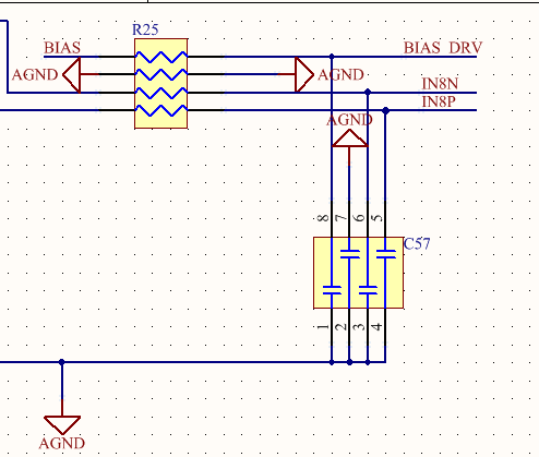
 )
)
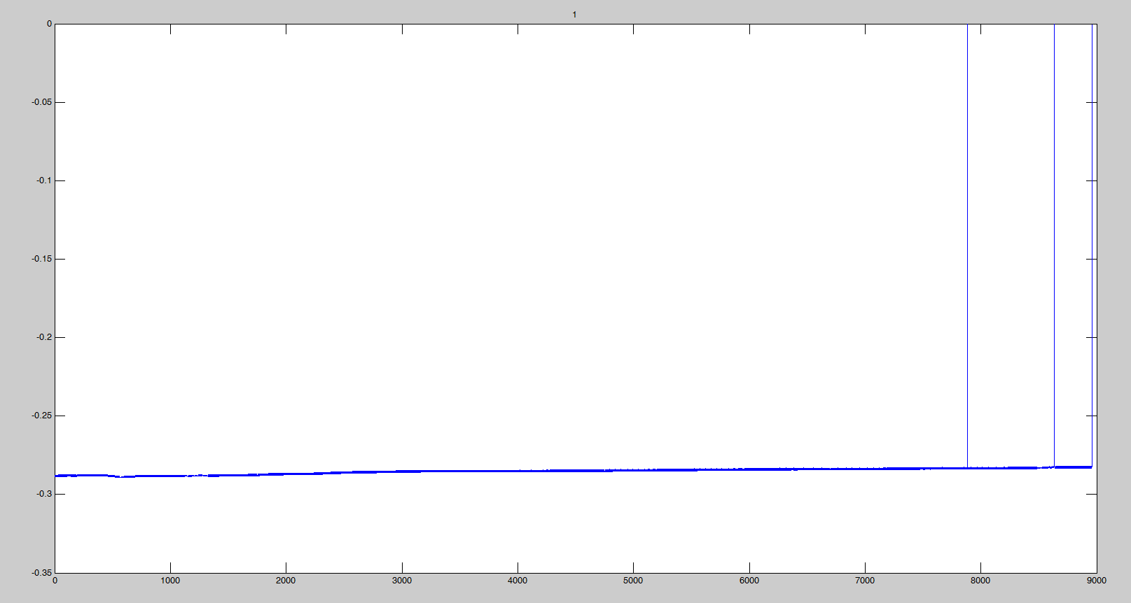
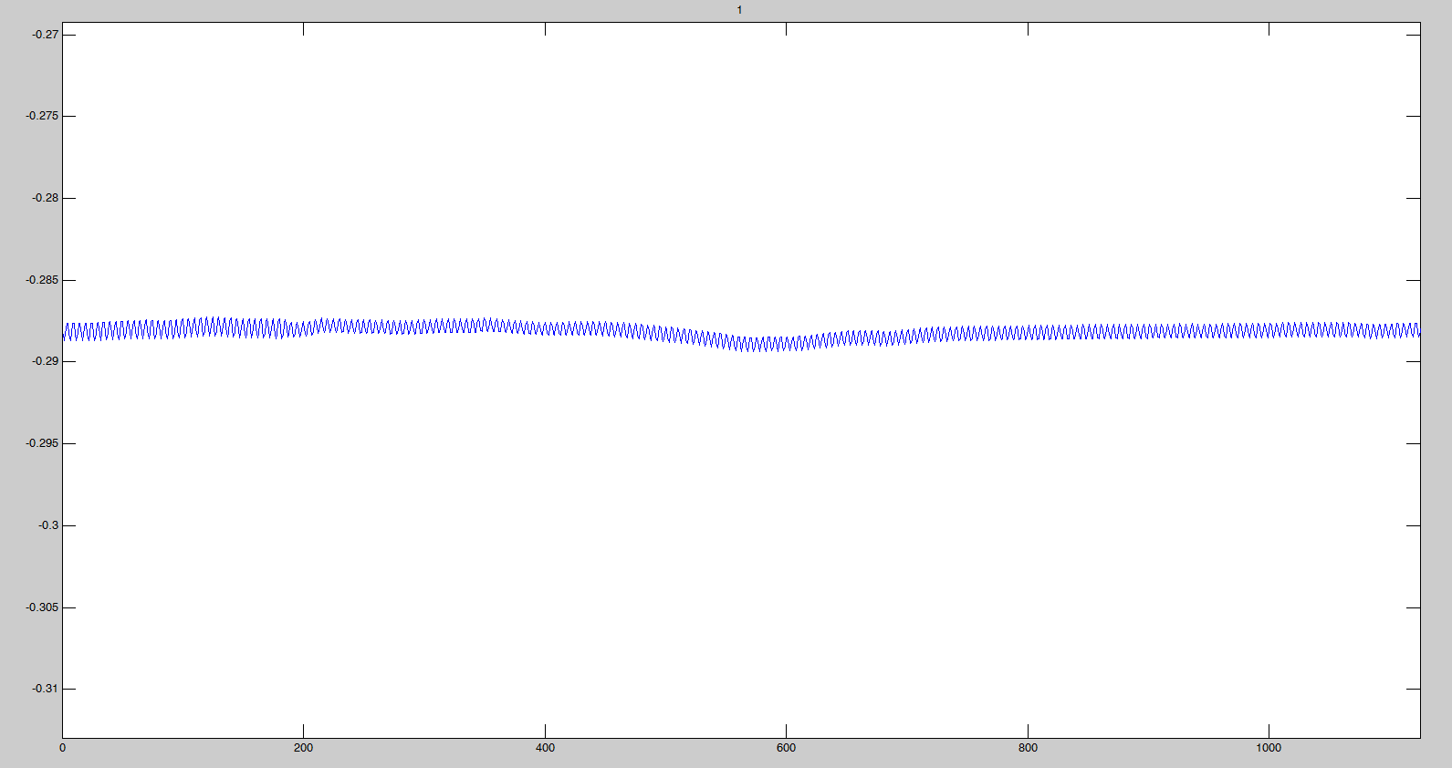
wave:X : point Y: uV
I have some question:
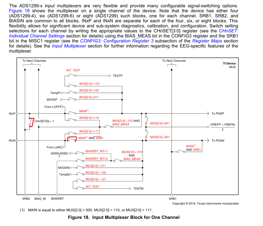
I want to make sure that my hardware circuit design is correct and my software configuration is correct?
Help me to check whether the hardware design of BIAS part is correct?
wave part :Why is the base drift so serious ? The valur are incorrect!
Could you please help me find out what the problem is?
