This thread has been locked.

If you have a related question, please click the "Ask a related question" button in the top right corner. The newly created question will be automatically linked to this question.

AFE5809EVM: dig_demodulator (enabled-disabled)

Part Number: AFE5809EVM
Other Parts Discussed in Thread: AFE5809

Hi guys, 

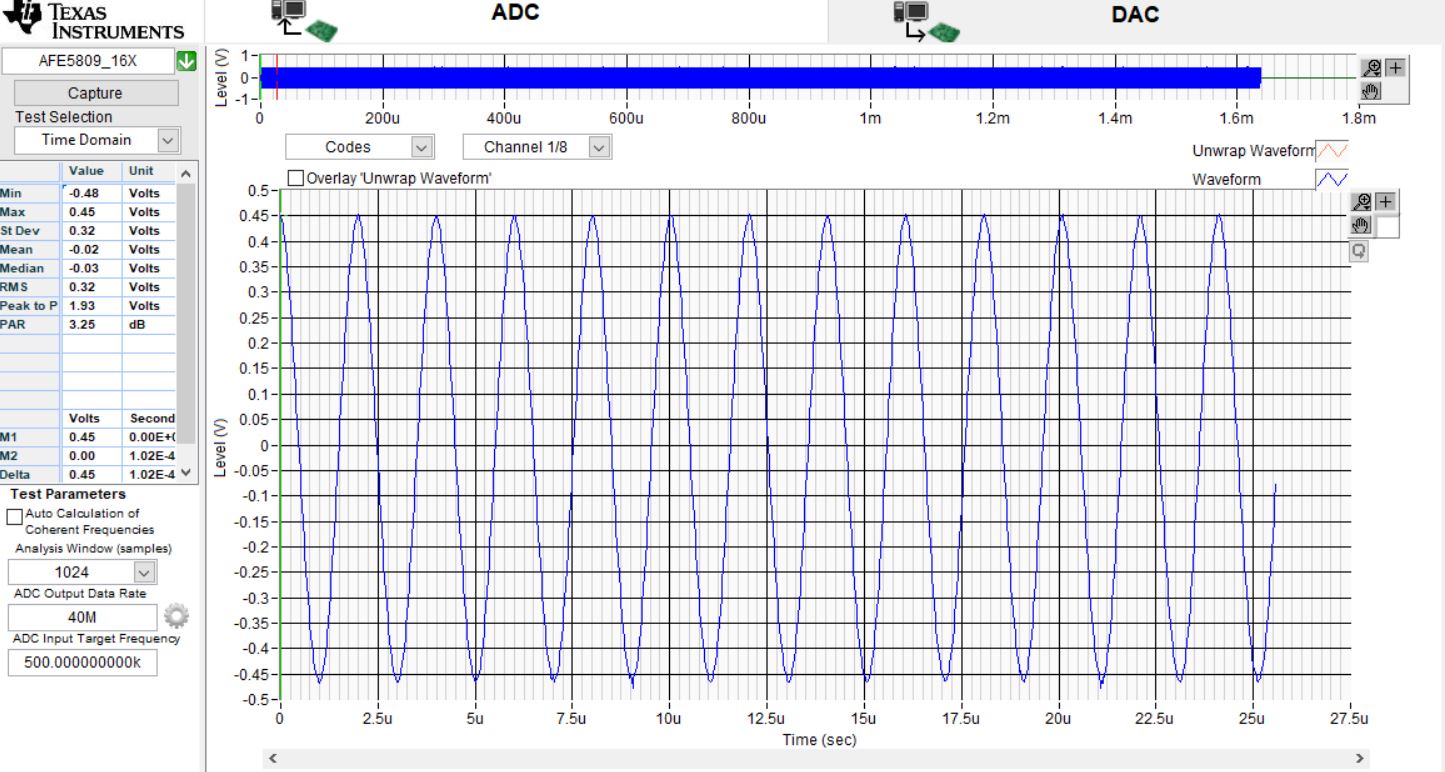
I have a basic query, I am testing the module in discussion, I attached some screenshots where we can see that when the DIG_DEMODULATOR is checked, the ADC module works normally, on the other hand unchecked DIG_DEMODULATOR we can see that the signal dies and becomes - 1, if someone can get me this doubt?, since I am slowly getting acquainted with this.

Regards

  • Mateo

    please refer to EVM user manual. When you run the demod test, you will need to apply a trig on TX_TRIG pin and also do extra steps for post-processing the captured data. 

    starting fro Page 11. user guide

    SLOU338A–October 2012–Revised November 2012
    AFE5809EVM Evaluation Module

    8.3 Step 3: Demodulator Mode
    The AFE5809 has a special demodulation and decimation mode whose main purpose is to reduce the LVDS data rate and improve overall system power efficiency. The device includes some built-in test modes to verify that demodulator block is working correctly.
    First, setup hardware as follows: • USB cable connected to both EVMs • External ADC clock enabled and used • Sync external clock to analog sine burst source • Connect analog input waveform to input channel 1 • Connect trigger from sine burst source that is synced with the analog signal to TX_Sync_in at J11 • Connect same trigger to TSW1400 EVM trigger input at J11

    Thanks!

  • I really appreciate your answer, but still unclear, I am only asking why this happen when I unchecked the box DIG_DEMODULATOR.

    I have another question for you guys, I have read the M=4 test .txt and I saw a list oF addresses, for example C3 C4 CA DF E0 E1 CE C0, and reading the datasheet (SLOS738E) I can't find anything related to these address, or again I miss something?

    thanks!

  • Digital demodulator is a seperate block. when it is on, we need to issue a TX_TRIG to make sure all Demod settiing are applied to the digital block. it is highlighted in the datsheet as below Page 72. 

    NOTE TI recommends to program the profile and filter RAMs before configuring other registers.

    A trigger is required to make new settings effective, such as profile RAM, coefficient RAM, and PROFILE_INDX Reg.0x0E[15:11] —either an external trigger event through the TX_SYNC_IN pin or a manual trigger event through Register 0[2].
    PROFILE_INDX Reg.0x0E[15:11] must be reprogrammed to ensure new profile and filter RAMs loaded correctly.
    ADC CLK is required during profile and coefficent RAM programming.

    in the M=4 files, it is not the address. they are filter coefficents. these filter settings were generated by matlab.  by using different filter cut off frequency, you may see different coefficents. they formated as Table 21 and Table 22 show in datsaheet. 

    Thanks!