Because of the holidays, TI E2E™ design support forum responses will be delayed from Dec. 25 through Jan. 2. Thank you for your patience.

This thread has been locked.

If you have a related question, please click the "Ask a related question" button in the top right corner. The newly created question will be automatically linked to this question.

ADS1299: Bias,Reference and Ground

Part Number: ADS1299
Other Parts Discussed in Thread: ADS1294R, ADS1298,

Hi

I am using the ADS1299 for an EEG application, I'm going to design a 16 channels single ended EEG system. I have the EVM board and checked whole ADS1299 datasheet and the EVM board Guide, and also some questions in forum. But yet, I have problem with something.

1- what should I do about my reference? as I read, i should turn on SRB1 in MISC1 register and simultaneously link the SRB1 pin to the reference electrode. is it correct?

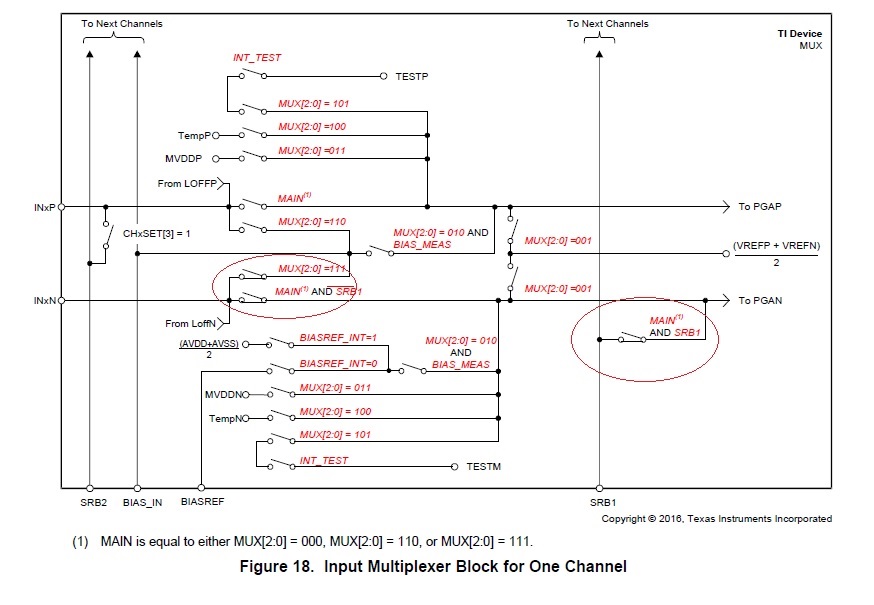
2-  I understand that I have to link just some of the BIAS_SENSs to the BIASINV to prevent saturating the channel. the problem is about the Bias signal, should I link BIASOUT and BIASIN pins? if we don't link them, where should PINOUT go and if link them, with respect to the below image the SRB and BIASIN pins are connected, what does it mean? and another thing that what is the effect of putting MUX[2:0] in 110 or 111 position? 

3- the last question is about the grounds. is it a relation between our reference and Bias and grounds? what should I do about my analog and digital grounds and how should I link them?

4- for this system, is there any pros for each one of daisy chain or cascade connection of 2 ads1299 s with eachother?

5- is there any important difference between connecting device to unipolar or bipolar supplies for this system?

Thanks

  • Hi Mojtaba,

    Thanks for your post and welcome to the forum! 

    1. If you're measuring single-endedly, yes. 

    2. You can also use mid-supply to generate the bias voltage. Please see the EVM schematic for how to configure the external device connections. 

    3. They can be tied together with a 0ohm resistor.

    4. No real difference outside of communication style and number of GPIO's used. Take a look at figure 70. in the datasheet for reference. 

    5. No, the performance is the same. 

  • Hi Alexander.

    Thanks for your answer.

    all of my issues are solved, except the second. let me have another question about it.

    actually I want to know about the effect of linking BIASIN and BIASOUT pins. what does happen if we link them in general and particularly in single ended mode when the SRB1 register is on and the MUX[2:0] is in one of 110 or 111 situations that mean according to the previous message image, the SRB pin and BIASIN pin are linked. 

    in total what does the BIASIN pin do and whats it's role?

    and about your answer, where we link the mid supply voltage? to link to the bias electrode of patient or BIASIN?

    Thanks again 

  • and there is another question about using multiple ads1299 s. I see this sentence in the forum:

    "If you are using the electrode inputs from all 4 ADS1299 devices to generate the common-mode, you simply need to short their BIASINV pins together and power down all but one BIAS amplifier." 

    it should be done in both cascade or daisy chain mode or it's just for daisy chain?

    Thanks

  • Hi Mojtaba,

    Happy to help! 

    The primary use for the BIASIN pin is to route the bias signal to any electrodes in case the bias electrode falls off.

    You can link mid-supply voltage internally using the appropriate register to change the MUX. Take a look at figure 33. 

    Take a look at 9.3.2.4.5.1 Bias Configuration with Multiple Devices in the datasheet. It's the same for both modes. 

  • Hi Alexander

    Actually I have read the whole datasheet containing the pages you said multiple times. but the last questions are yet remained.  if it is possible I need more description than datasheet about these questions.

    Thanks again

  • Hi Mojtaba,

    I'll try to be more clear.

    Q: in total what does the BIASIN pin do and whats it's role?

    A: In the event that the BIAS electrode becomes disconnected from the patient, by having BIASOUT connected to BIASIIN, the BIASOUT signal can be routed through BIASIN and back to the patient through one of the input electrodes. This way, the patient stays biased and the measurements stay within the common-mode input range of the PGA. Of course, one measurement will be "lost" since it's being used to bias the patient.

    Q: it should be done in both cascade or daisy chain mode or it's just for daisy chain?

    A: it's the same for both modes. 

  • Hi alexander

    Thanks for your answers.

    another question I faced is that what is the difference of single shot mode and rdata in use. cboth off them give us outputs with our commands.

    Thanks again

  • Thanks so much.

    I think this will be the last question!

    in cascade mode is it possible to use one of the internal clocks as general clock for all devices, like as daisy chain mode?

  • and about daisy chain, i think this figure in datasheet may have some trouble.

    as noted in this figure, we have 216 bytes in 216 clock including status bytes and the channels. but for the second device why they are only 120 bytes from 217 to 337. it means it has only 4 channels of 24 bits+24 status bit, or other thing?

    Thanks

  • I think my questions will not finish forever!!

    about this comment of Ryan

    according to datasheet what is Rflt,Cflt and  Rfilt?

  • Hi Mojataba,

    Yes, you can use a similar clock configuration. Take a look at 10.1.4.2 Daisy-Chain Mode for a spi connection diagram. 

    This is just showing how many SCLKs to send for an 8 channel device and then a 4 channel device. This is the most common way to daisy-chain/cascade our devices as it allows for a 12-lead ECG measurement + respiration when using the ADS1298 + ADS1294R. 

    Take a look at the schematic for the ADS1299EEGFE-PDK for an example of component values: http://www.ti.com/lit/ug/slau443b/slau443b.pdf

    If you have additional questions, please start a new thread. 

    http://www.ti.com/lit/ds/symlink/ads1299.pdf