This thread has been locked.

If you have a related question, please click the "Ask a related question" button in the top right corner. The newly created question will be automatically linked to this question.

ADS8678EVM-PDK: from the software "ADS86xx EVM GUI", cannot display correct wareform, for instance, wrong amplitude,wrong function .etc

Part Number: ADS8678EVM-PDK

Hi

    we buy an ADS8678EVM-PDK Evaluation Module from IT.  we followed the "ADS8678EVM-PDK Evaluation Module user's guide" , set all jumper as default configuration describled in Table 13,except  we keep J17 open for generating HVDD and HVSS using an onboard switching regulator as saying in Table 10.

   100KHz  sinusoidal wave is the waveform that we need to be sampled in practical application. In theory, the board has 500ksps  sampling rate, which can meet the demand. But according the test results in the  experiment we do not know  whether our operation is wrong or whether we bought a bad board.

   when we begin our test, we stick ADS8678EVM and the simple capture card together, the simple capture card connect to PC using an usb line,5V is given to  ADS8678EVM on J32 using an DC power supply, using singal source(Tektronix AFG3022C) generate waveform, connet positive electrode to AIN0+,   connet negetive electrode to AIN0- , at the same time, an oscilloscope is connected to the input end of the signal.  we have problems during the test.

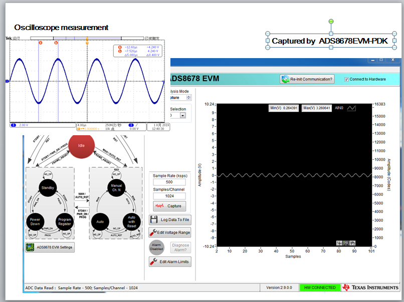
 case1: signal source:20kHz - sine wave, Vp-p=9V, problem: the amplitude showing on the GUI is obviously smaller than the actual signal


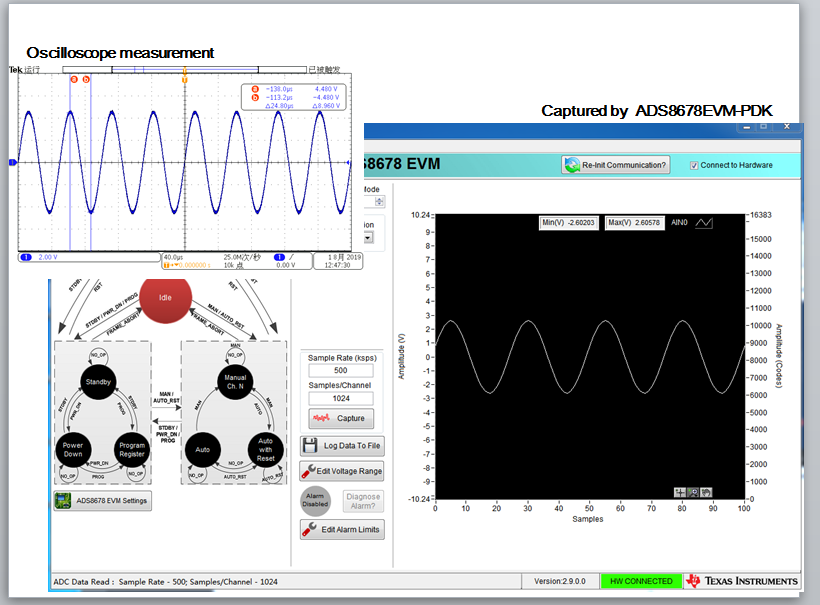
case2: signal source:100kHz - sine wave, Vp-p=8.5V, problem: the amplitude showing on the GUI is obviously smaller than the actual signal, seem to be limited 

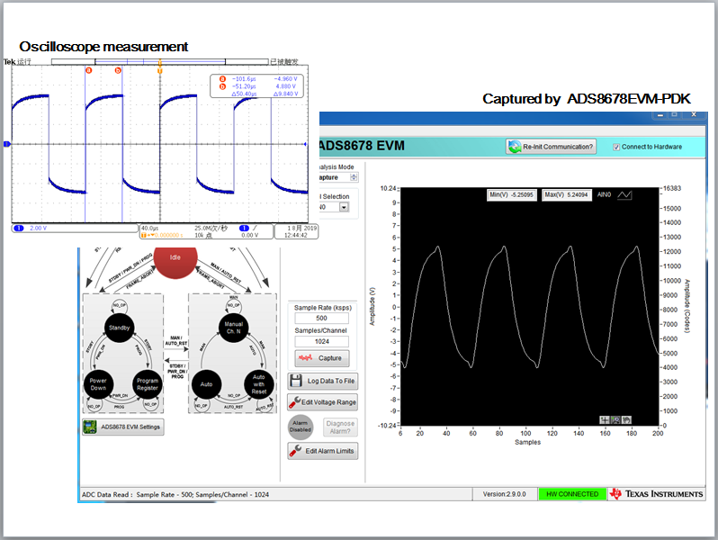
case3:signal source:10kHz - square wave, Vp-p=10V, problem: the waveform is seriously distorted. It doesn't look like a square wave, but rather like a sine wave.

  • Hello user4076865,

    Firstly,  the amplifier U4 on your board was bypassed and you did not use the front-end amplifier because the default jumper on J8 is short between pin 2 and 3  also J25 is open which means the signal is not connected to the amplifier U4. Secondly, your 100kHz input signal can not be used for this ADS8678 ADC because the bandwidth of internal analog filter is limited to 15kHz (see specification on page 8 in ADS8678 data sheet). Hence, please check:

    1. The supply voltage on pin 9 and pin 30 of U2, also pin 34 of U2.
    2. The ref voltage on pin 5 of U2.

    If all of these voltages are correct on your board, I suggest to do the test without amplifier firstly on the EVM board, no external power supply and just use the supplies from SDCC card and USB port. Please make sure:  Jumper J8 on pin 3 and pin 2, J22 is shorted, J25 is open. J13 short on pin 2 and pin 3. J17 is close. Both J12 and J14 are short on pin 2 and pin 3. Then, apply a 1kHz sinewave signal (≤±10Vpk) to Pin 6 and Pin 5 of J7, then capture the data and check the waveform and data in the EVM GUI. It should work.

    Next, if you want to use the amplifier on the board, put the jumpers on the right positions and check if the supply voltages on pin 8 and pin 4 of U4 are correct after applying a external power supply, then a connect proper frequency(e.g. 1kHz) input signal to the board, capture and check in the GUI again.

    Please let me know if you have more questions, thanks.

    Regards,

    Dale