This thread has been locked.

If you have a related question, please click the "Ask a related question" button in the top right corner. The newly created question will be automatically linked to this question.

ADS122C04: Best methods to shield circuit from inductive induced noise for Precision load sensing application .

Part Number: ADS122C04


Hi,

We use a Half-bridge and a full bridge load sensor for our sensing application. We have a very high Inductive environment due to an induction coil. What are the best ways to keep noise from inducing noise board via the load sensor wires?

On the PCB I was thinking of adding ferrites on the input to the ADC pins and using a copper braid shielding on the wires. The frequency at which the coil works is around 20-30Khz.

Tony.

  • Hi Tony,

    Keeping external noise out of a load cell measurement is one, if not the most, difficult task within the system.  Most of the noise is being picked up in the wiring.  For this reason this should be your first line of defense against EMI/RFI.  Braided shielding will help if there are no exposed areas and the braided shielding is properly terminated at the PCB.  In particular, be careful at the connector where the wires leave the shielded environment.  And make sure the shield ground does not influence the analog ground.

    Ferrites are also useful, but the peak loading is set to higher frequencies like 100MHz.  Most likely ferrites will not show a benefit at 20k-30kHz frequencies.  Instead you may find a 2nd order RC filter to be of greater benefit. 

    Remember that EMI/RFI can get into the excitation and power supplies as well which can also affect performance.

    Best regards,

    Bob B

  • Hi Bob,

    Thanks for your inputs on this.

    I have one more doubt about the grounding of the system.

    Is it beneficial to have a floating (isolated) ground or is it better to tie the earth ground and the system ground together to keep EMI away?

    Regards,

    Tony.

  • Hi Tony,

    Earth ground may be a good idea if the shield is connected to the earth ground.  The consideration here is potential relative to the earth ground and any potential ground loops that can cause further interference.

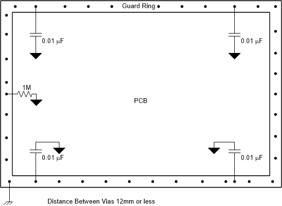
    One potential method is to use the concept of a guard ring.  The shield would connect to the guard ring (which could also could be connected to earth ground).  The remainder of your circuit would be inside of the guard ring.  The analog and digital grounds should not directly connect to the guard ring accept through the impedance connections of the capacitors and a high Ohm resistor (shown here as 1M).

    Best regards,

    Bob B