


Hi,
Following the thread:
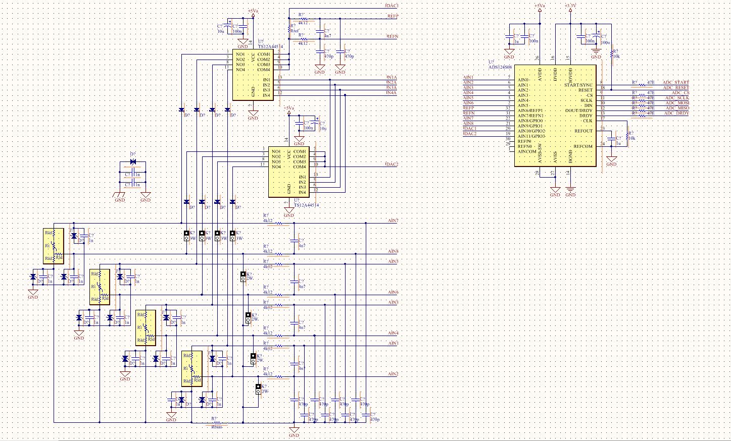
With the schematic:
Trying to read the temperature off the internal diodes in the ADS124S08, at a loss what to do next, unable to read valid data.
What I am doing:
* Pull down RESET
* Release RESET
At this point, I can read the register contents, they match the default register values defined in the datasheet.
* Wait for RDY bit
* CLear FL_POR
* Enable the Temperature sensor (Reg 0x09)
* Enable PGA (Reg 0x03)
* Limit PGA gain to 4 (Reg 0x03)
* Send START OPCODE
* Set START Pin High
* Check DRDY
* Send RDATA OPCODE
* Read Data out
I get blank data at this point.

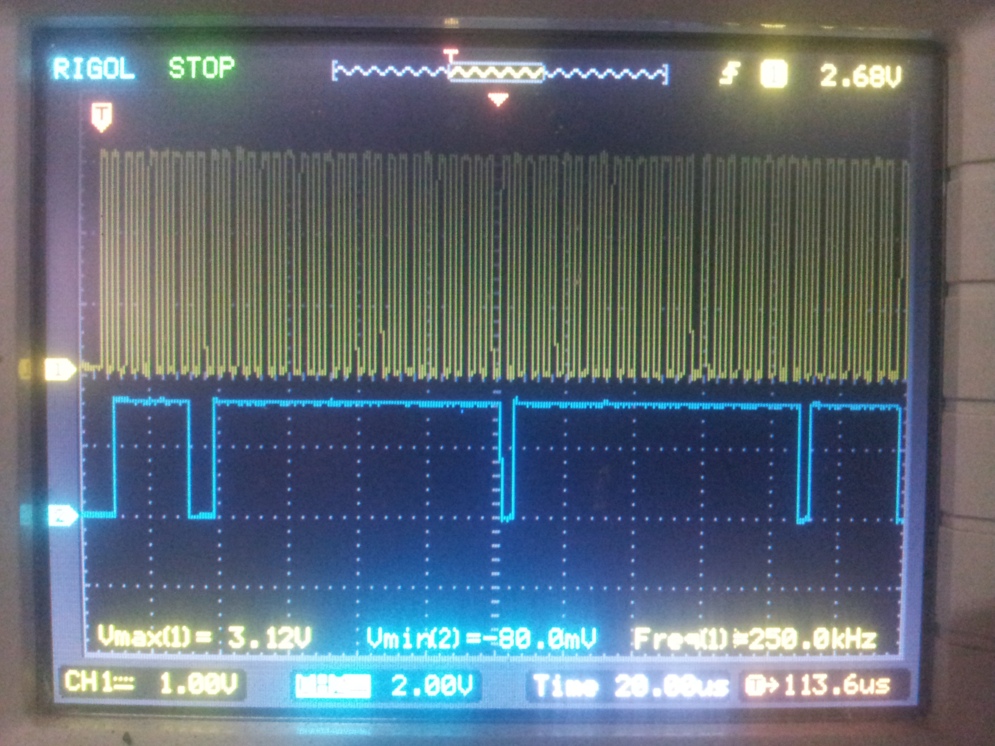
I can confirm the same data on the SPI bus (SCLK and MISO lines). Do I need to do anything more setup, to get valid data from the temperature sensor ?
Have gone through the datasheet, looking for specific setup for the temperature sensor. I couldn't find any.
Can someone please tell me what I am doing wrong ?
Code, reading the sensor:
void ads124xxx_reset(void)
{
	printf("* %s: ADC Reset\r", __func__);
	__ADC_RST_ENA();
	delay(5);
	__ADC_RST_REL();
	delay(5);
}

void ads124xxx_dump_regs(SPI_TypeDef *SPIx)
{
	uint16_t i, dat;

	printf(" ----------------- \r");
	printf(" Register Map\r");
	printf(" ----------------- \r");
	for (i = 0; i < 0x12; i++) {
		dat = ads124xxx_spi_regrd(SPI1, i);		/* Read register */
		printf(" Reg %02xh: %02xh\r", i, dat);
	}
	printf(" ----------------- \r");
}

void ads124xxx_init(SPI_TypeDef *SPIx)
{
	uint8_t tmp;

	printf("* %s: Initializing\r", __func__);
	while (ads124xxx_spi_regrd(SPI1, 0x01) & 0x40);		/* wait for RDY */

	tmp = ads124xxx_spi_regrd(SPI1, 0x01);
	ads124xxx_spi_regwr(SPI1, 0x01, (tmp & ~(1 << 6)));	/* clear FL_POR */

	/* Write all relevant ADC configuration here */
	/* Read back configuration and verify */
}


/**
 * Measure internal die temperature
 */
void ads124xxx_temp_sense(SPI_TypeDef *SPIx)
{
	uint8_t tmp;

	/**
	 * When measuring the internal temperature sensor,
	 * the analog inputs are disconnected from the ADC and the
	 * output voltage of the temperature sensor is routed
	 * to the ADC for measurement using the selected PGA gain,
	 * data rate, and voltage reference. If enabled, PGA gain
	 * must be limited to 4 for the temperature sensor measurement
	 * to remain within the allowed absolute input voltage range
	 * of the PGA.
	 */
	tmp = ads124xxx_spi_regrd(SPI1, 0x09);
	tmp |= (0x02 << 5);					/* Temperature sensor enabled */
	ads124xxx_spi_regwr(SPI1, 0x09, tmp);

	tmp = ads124xxx_spi_regrd(SPI1, 0x03);
	tmp |= (0x01 << 3);					/* PGA enabled */
	tmp |= 0x02;						/* limit PGA gain to 4 */
	ads124xxx_spi_regwr(SPI1, 0x03, tmp);

	ads124xxx_spi_cmd(SPI1, START_OPCODE_MASK);		/* START(0x08) conversion */
	GPIO_SetBits(GPIOC, GPIO_Pin_10);			/* START Pin enable */
	printf("* %s: ADC set to continuous conversion\r", __func__);
}

int main (void)
{
	SysTick_Config(SystemCoreClock / 1000);			/* SysTick event @1ms */
	gpio_setup();
	USART1_Init();						/* for IO redirection */
	spi_setup();

	printf("\r -----------------\r");
	printf(  " ADS124xxx Test\r");
	printf(  " -----------------\r");

	ads124xxx_reset();					/* RESET ADC */
	ads124xxx_dump_regs(SPI1);
	ads124xxx_init(SPI1);					/* START conversion */
	ads124xxx_temp_sense(SPI1);

	while (1) {
		GPIOB->ODR ^= GPIO_Pin_6;			/* Toggle LED */
		delay(500);
		ads124xxx_spi_datrd(SPI1);
	}
}
Thanks,
Manu


