This thread has been locked.

If you have a related question, please click the "Ask a related question" button in the top right corner. The newly created question will be automatically linked to this question.

ADS1261: Where to get the firmware source code of ADS1261EVM?

Part Number: ADS1261


Hi,

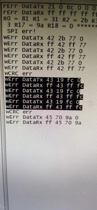
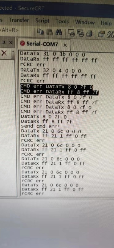
My customer met a trouble to control their own  ADS1261 board [a certain probability can't read or write correctly through SPI ]. I tried to locate and reproduce the issue.  I just got a ADS1261EVM , but the EVM GUI is not that flexible.

I think a simpler approach is to slightly modify the code of TM4C129 on the EVM,  such as  changing the SPI speed, specific sequence of commands, and so on. Also, the JTAG interface of TM4 is open . Would you please sharing this firmware code to me ?  thanks. 

Also  I noticed that there is a test code,ADS1261 Example C Code Software,  which TI platform did it test on? Is there any guidance to quickly set up  and run on ADS1261EVM? 

  • Hi Yue,

    Unfortunately, we don't have a complete EVM firmware project that we can share with customers. However, if there is something you need to debug or test it may be possible for us to help. Please let me know what it is you'd like to test, or which parts of the SPI configuration you'd like to have more control over and I'll see what I can do to help...

    As for the ADS1261 Example C Code, it is a subset of the actual EVM Firmware. When used with a TivaWare DriverLib project it shouldn't be too difficult to build up a working CCS project that communicates with the ADS1261.

  • Hi Chris,

    I don't have a TIVA EVM and not that familiar with this device. Can you set up a demo based on simplink platform device or msp430?   I need a solution to locate this issue. thanks. 

    My customer is using a STM32 MCU and  ADS1261 Example C Code Software to drive ADS1261, they are doing evaluation of this device. now, they are doing repeated register reading  and writing test.  In most cases , they all got the right response. but,sometimes, they got crc error response,this symptom occurs every a few tens of seconds. which they seldom encountered this using other device before. so far, they did a lot test, slow down or speed up SPI speed(1.6M to 4M), increased the interval of each commands, but this problem still occur.

    I tried to use EVM and GUI to reproduce this, but the tool is no that flexible, for example, I can do the repeated test with the script.

    Below are the error print. only wrong response will be print out.


  • Hi Yue,

    I think we should try to collect more information from the customer before trying to replicate it, otherwise it will be very unlikely that we'll succeed in doing so.

    For starters, what is (command) pattern they are sending, and how often are they sending these commands?...it looks like they are performing repeated RREG and WREG commands.

    Can you also have the customer look at the SPI communication on a logic analyzer or oscilloscope? It would be most helpful if they could capture an SPI frame with a CRC error. If the error is infrequent enough, they might need to configure their micro to toggle a GPIO pin when the CRC error is detected.

    What stands out initially to me is that the "echo byte 2" recieved does not always match the "arbitrary" byte they transmitted, as shown below:

    Echo byte 1 appears to be okay most of the time except when DataRx = 0xFF, which would indicate that the device is not responding at all. In this case, it is import to check the /CS, /RESET, and /PWDN pins to ensure that the device is active and selected on the SPI bus. If there are other devices on the SPI bus, then they may need to check if other devices are active and holding DOUT high.

    Echo byte 2 seems to be incorrect more often. Since this data is getting printed to a terminal, I cannot tell if the SPI communication is the issue or if the code that prints this data to the terminal is causing the issue. Therefore, it is important to determine if this the data printed to the terminal is correct and if the same mismatch is occurring on the DIN and DOUT pins.

    If the data is getting corrupted on DIN/DOUT, then I would pay attention to whether the SCLK/DIN/DOUT signals are clean or if there are large noise spikes that bit be causing transmission errors. Also, check if any other device's /CS pin (sharing same SPI bus) is getting enabling during this time.

  • Thanks for the suggestion.  the idea to handle the  infrequent error is great and the interval, I forgot to mark,is 10 ms . and only one SPI slave device in their test. 

    To be honest, a a testable environment is important to me , not only to a fast verification, but also for me to  quick learning this device. looks like I have to get a logic analyzer  and on-site test with them even they did not use our MCU。

  • Hi Yue,

    Please do keep us posted on your progress.

  • Tom,

    I on-site supported them, turns out there is a little bug in TI offered reference code. after this modification, so far, no further issue reported. 

    /* (OPTIONAL) Write to all registers */

    uint8_t startIndex = REG_ADDR_STATUS;

    uint8_t count = NUM_REGISTERS - startIndex;

    writeMultipleRegisters(startIndex, count, &initRegisterMap[startindex]);

    void writeMultipleRegisters(uint8_t addr, uint8_t count, const uint8_t data[])

    {

    /* Check that register map address range is not exceeded */

    assert( (addr + count) <= NUM_REGISTERS );


    uint8_t i;

    for (i = addr; i < (addr + count); i++)

    {

       writeSingleRegister(i+addr, data[i]);

    }

    }


    Changed to :----------------------------------------------------------------------------------------


    /* (OPTIONAL) Write to all registers */

    uint8_t startIndex = REG_ADDR_STATUS;

    uint8_t count = NUM_REGISTERS - startIndex;

    writeMultipleRegisters(startIndex, count, initRegisterMap);


    /* (OPTIONAL) Read back all registers */

    readMultipleRegisters(startIndex, count, ADC_RegisterMap);


    void writeMultipleRegisters(uint8_t addr, uint8_t count, const uint8_t data[])

    {

    /* Check that register map address range is not exceeded */

    assert( (addr + count) <= NUM_REGISTERS );


    uint8_t i;

    for (i = addr; i < (addr + count); i++)

    {

       writeSingleRegister(i, data[i]);

    }

    }