This thread has been locked.

If you have a related question, please click the "Ask a related question" button in the top right corner. The newly created question will be automatically linked to this question.

ADS7853: Extra Receive Frame

Part Number: ADS7853
Other Parts Discussed in Thread: MSP430F249,

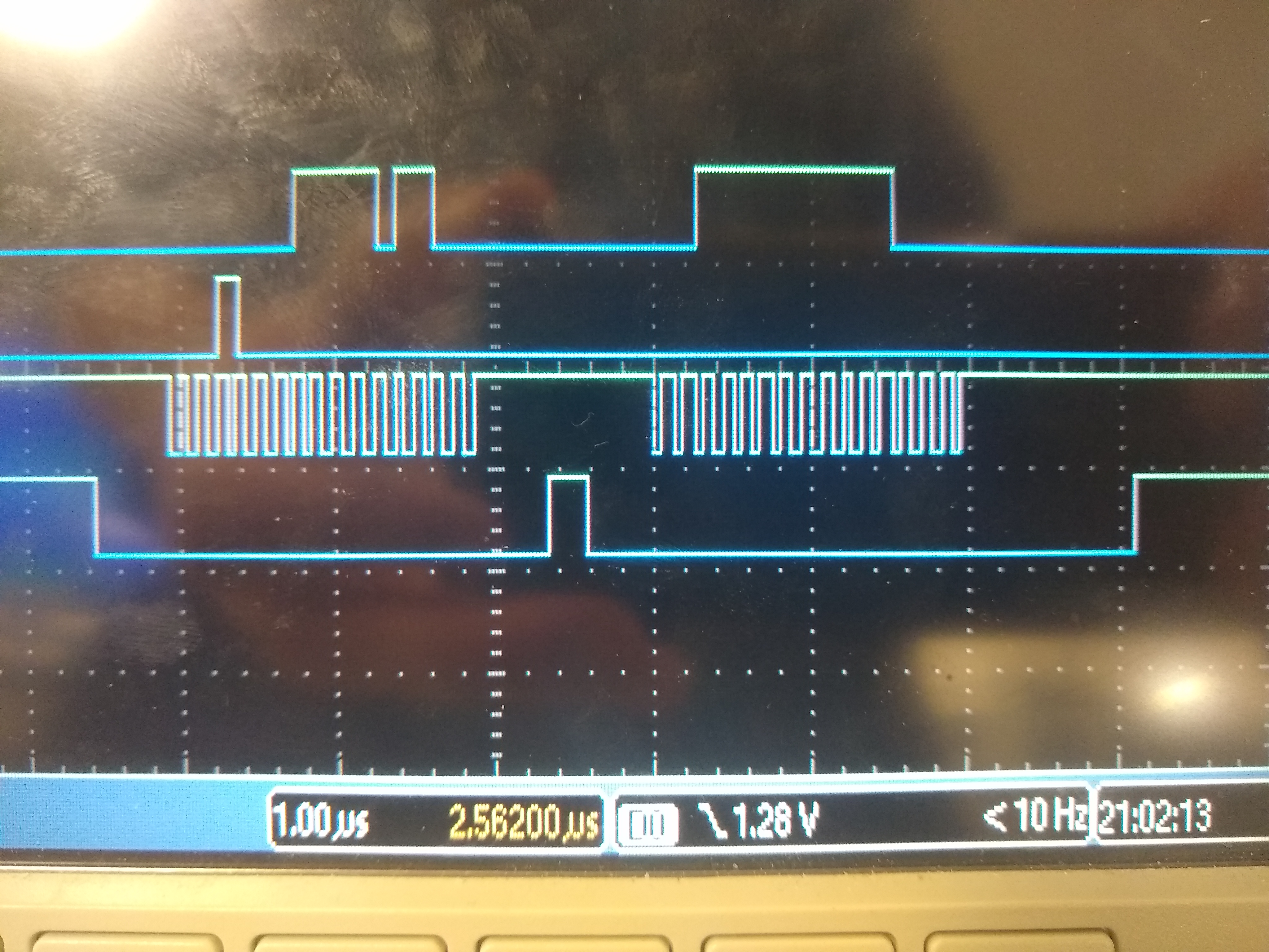
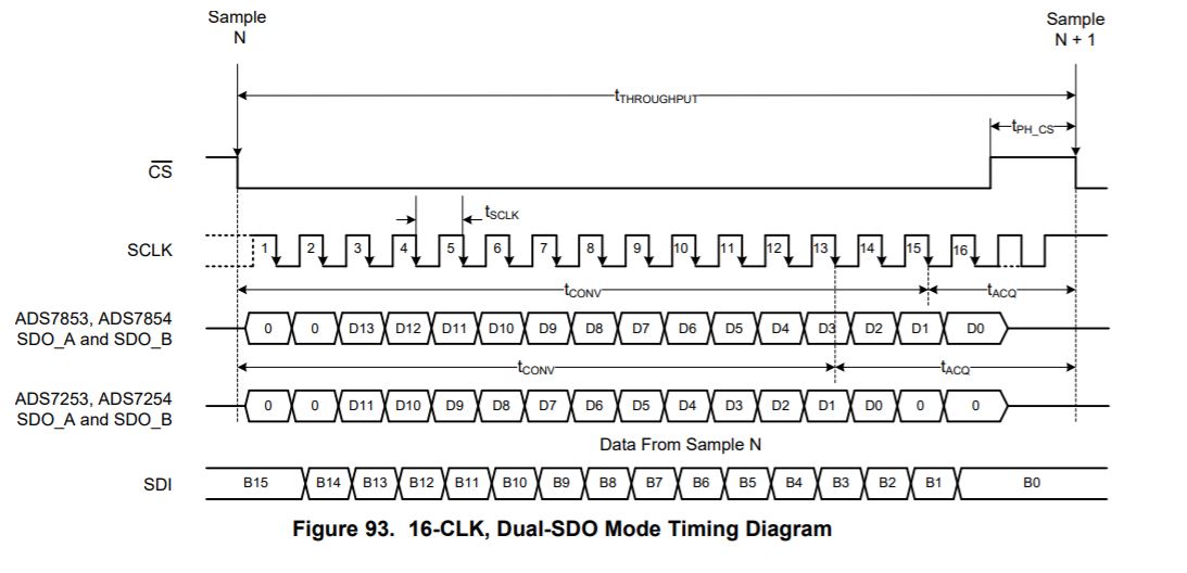
I'm using an ADS7853 with an MSP430F249, and I seem to get an extra frame when I talk to it. I am running the ADS7853 in 16-CLK Dual SDO Mode with 16 CLK cycles per frame, however after I run the first frame and receive my data I get data on the second 16 CLK frame. Without this second frame that block of data will move over to the first frame and I get no data back. Is this second frame necessary? From reading the data sheet I was under the impression that you only needed one frame to read the ADC register. I have attached two pictures of my scope; one with the two 16 CLK frames and one with only one frame. Also, the command I am sending the chip is 0001_0000_0000_0000.

Thanks yall


  • Hi Jon,

    Thanks for your post.

    Can you please confirm which signals you are showing (from top to bottom)?

    • 3: DOUT
    • 2: DIN
    • 1: SCLK
    • 0: /CS

    Please refer to section 8.5.3.1 in the data sheet. Figure 90 illustrates that the command is sent in one frame and the register contents are output on SDO_A in the next frame. 

    Also, regardless of the minimum required SCLK falling edges per frame (N as listed in Table 4), the number of clocks required for register readback operation is fixed to 48 for all interface modes. This is shown in frames F+1 and F+2 below.

    Best regards,

  • From top to bottom:

    MISO

    MOSI

    CLK

    CS

    In regards to the datasheet, this was the part in which I was looking at (Figure 93) for the 16-clk mode. So If I want to read the conversion results I need to configure my control register to 16-clk dual mode and then each conversion read will be 16 clks?

    EDIT: I misspoke at one point in the question, I am looking to read the ADC conversion results, not the ADC Register. I think I confused the two when I made this post originally.

  • Hello Jon,

    Yes, once you've configured the device for dual-SDO Mode, you may use Figure 93 as a reference for reading conversion results. 

    To confirm that you have configured the device for 16-CLK, dual-SDO mode, read back the CFR register contents by sending 0011b followed by 000h as shown in Figure 90 and Table 9. Note that frames F+1 and F+2 must use 48 clocks. Remember that, to enter dual-SDO Mode, you will have to write to the device using the default 32-clock mode first. This will require 32 SCLK falling edges to write the new register value to the CFR register. For 16-CLK, dual-SDO Mode, please write 1000 1000 0000 0000 (8800h) to the device. The first four bits (1000b) indicate you wish to write to the CFR register, followed by the 12-bit register value.

    Best regards,

  • This was my issue, thank you! I confused a conversion read with a register read. I am now seeing my conversion data in 16-clk dual mode.