This thread has been locked.

If you have a related question, please click the "Ask a related question" button in the top right corner. The newly created question will be automatically linked to this question.

DAC8760: problem with two devices in spi daisy-chain

Part Number: DAC8760

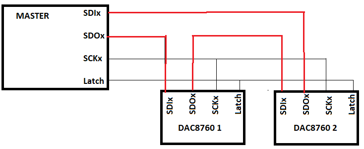
I have 2 DAC8760 devices connected in daisy-chain, the 2 are configured in 10 volts of output,
the first one is correct, but the second does not exceed 3 volts.
its the same configuraration,i send in 48 bits frame , but only the first works.

  • Hi Ernesto,

    Can you share your schematic?

    Are you enabling daisy-chain mode in the register map?  You must set that bit for daisy chain to work.

    Thanks,

    Paul

  • here is my code and ugly diagram.

    //Control Reg
    LATCH=0;
    SPI2_Send24_Bits(0x55,0x10,0x09);
    LATCH=1;

    //Conf Reg
    LATCH=0;
    SPI2_Send24_Bits(0x57,0x00,0x00);
    LATCH=1;

    //Gain Reg
    LATCH=0;
    SPI2_Send24_Bits(0x58,0x00,0x00);
    LATCH=1;

    //Gain Zero Reg
    LATCH=0;
    SPI2_Send24_Bits(0x59,0x00,0x00);
    LATCH=1;

    //Control Reg
    LATCH=0;
    SPI2_Send24_Bits(0x55,0x10,0x09);
    SPI2_Send24_Bits(0x00,0x00,0x00);
    LATCH=1;

    //Conf Reg
    LATCH=0;
    SPI2_Send24_Bits(0x57,0x00,0x00);
    SPI2_Send24_Bits(0x00,0x00,0x00);
    LATCH=1;

    //Gain Reg
    LATCH=0;
    SPI2_Send24_Bits(0x58,0x00,0x00);
    SPI2_Send24_Bits(0x00,0x00,0x00);
    LATCH=1;

    //Gain Zero Reg
    LATCH=0;
    SPI2_Send24_Bits(0x59,0x00,0x00);
    SPI2_Send24_Bits(0x00,0x00,0x00);
    LATCH=1;


    //value of outputs
    LATCH=0;
    SPI2_Send24_Bits(0x01,0xff,0xff);//9.98 volts
    SPI2_Send24_Bits(0x01,0xff,0xff);//3.1 volts

    LATCH=1;
    LATCH=1;

  • Hi Ernesto,

    You should confirm a couple of things:

    1. Is this wired correctly? I personally do not like the SDI/SDO naming convention for this reason.  You have pins on the master called SDO and SDI, but SDO and SDI mean Slave-Data-In and Slave-Data-Out.  So in your diagram, you have a pin on the master called SDI but connected to the SDO pin, which is confusing.  I would confirm on the master if the pins are MISO or MOSI.  You could monitor the wire that connects DAC1 to DAC2 and verify that the data is on the correct format.

    2. Verify with a scope that your timing is valid.  I have seen in the past that some MCUs will buffer the SPI data, so the function SPI2_Send24_Bits may return but the command is not done being physically set.  You might have a polling function in your write command that checks that the writing is complete, but that is often overlooked.  You might notice that the LATCH line is going high before the command is complete.  

    Does a read command work from both devices?

    Thanks,

    Paul

  • Any updates?