This thread has been locked.

If you have a related question, please click the "Ask a related question" button in the top right corner. The newly created question will be automatically linked to this question.

ADC128S102: something strange -- Dout are clocked out on the rising edges of the SCLK

Part Number: ADC128S102

Hello, We take the 'Vout' value with FPGA, and foud the numerical value sometimes quite different from the reality.

So we captured the waveform with an oscilloscope like this:

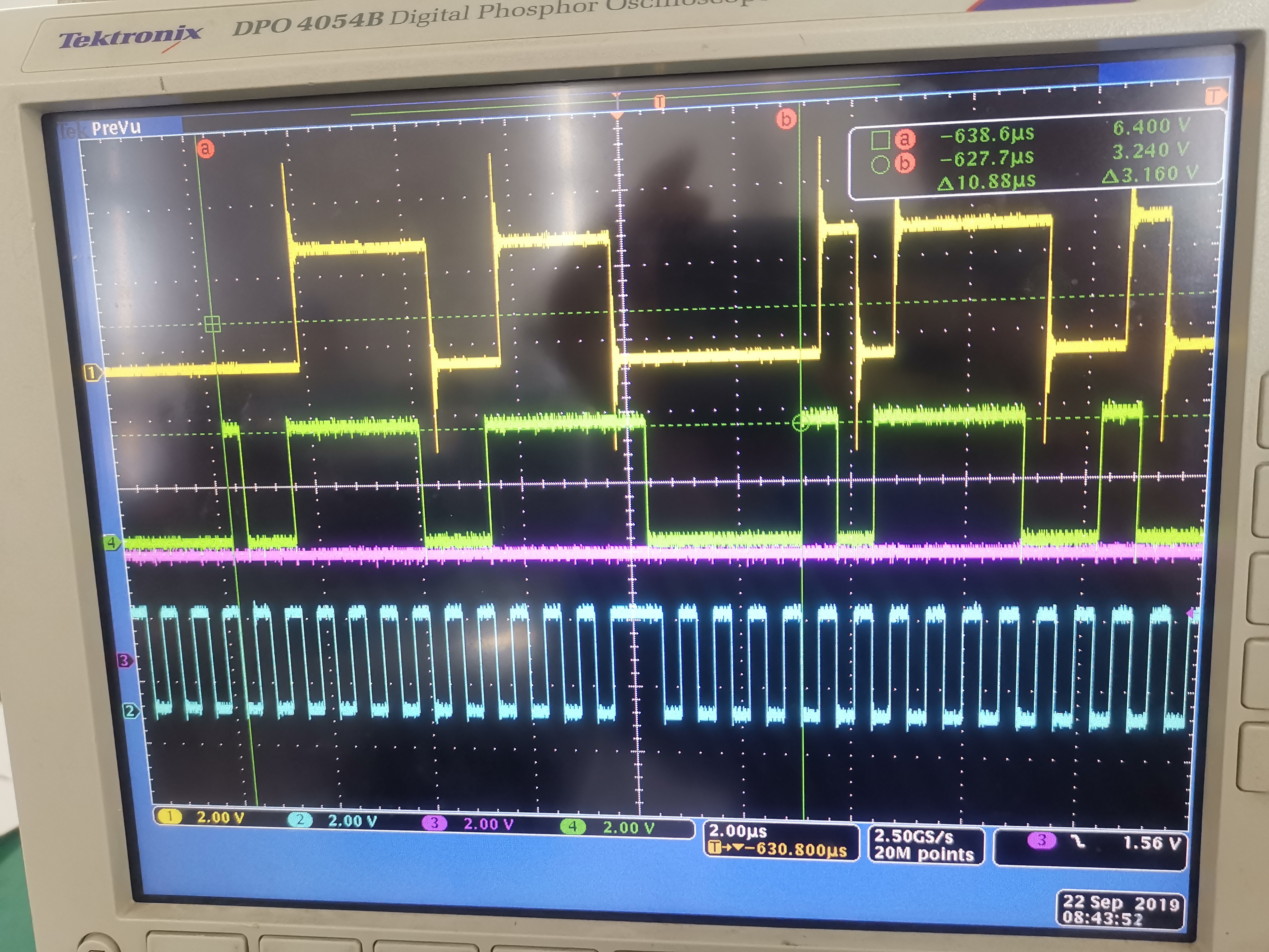
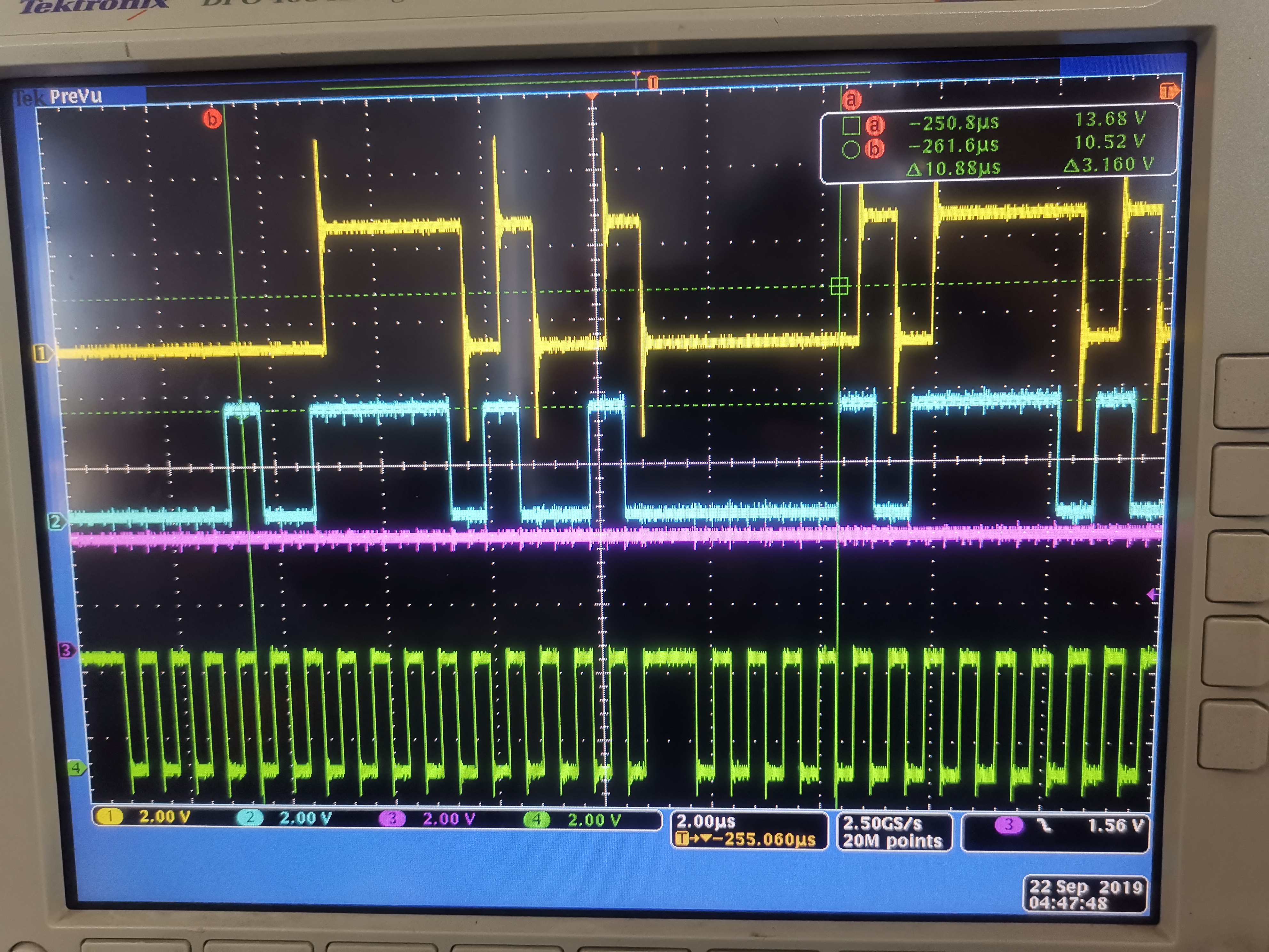
In the figure above, from top to bottom: Data collected by fpga through SCLK rising edge, Dout, Don't care(we use it to track strange anomalous value) , SCLK

The two green rulers are marked at the beginning of each DOUT. And the sequence starting at ruler B is correct, it should be (10111...), something strange have appeared in the sequence which beginning at the ruler A, some Dout output samples are clocked out on the rising edges of the SCLK

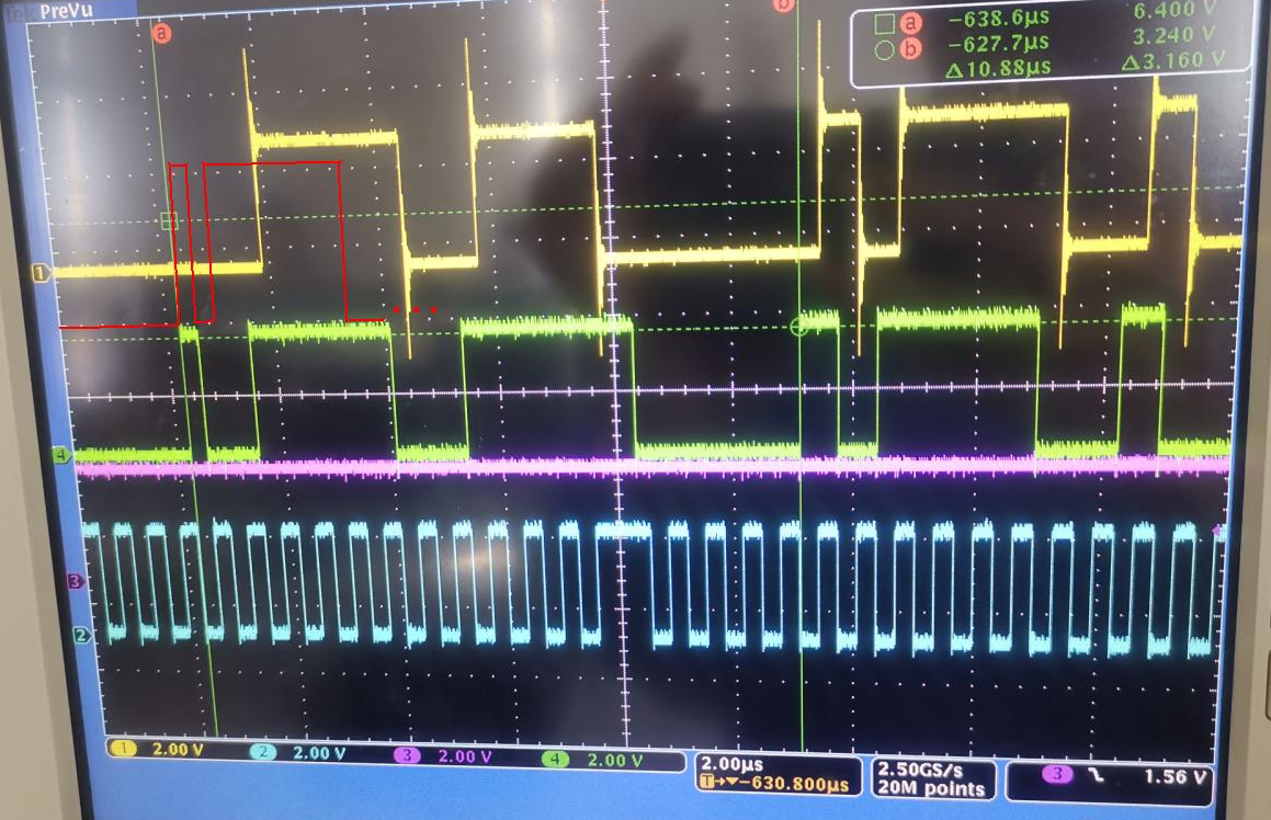
At first, we suspected that the ADC128S102 had caught the falling edge feature by mistake on the rising edge of SCLK, if this is the case, the later wave forms will also move forward(As the red line marked in the picture below), It won't miss the falling edge next to. But the reality is: the high level(1) lasted half a cycle and low level(0) lasted one and a half cycle.

The waveforms of CS and DIN are not shown in the figure above, normally aaaa is shown below:

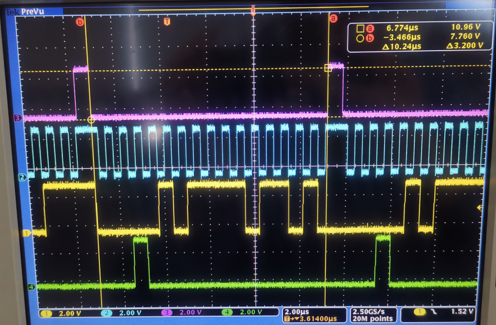
from top to bottom: CS, SCLK, DOUT, DIN

Can you give an explanation or suggestion about this? 

The current SCLK  frequency is 1.5625Mhz. Is the strange related to this?  (Even though it's related to the strange, also want to know why it happened)

Thanks,

Luddy

  • Hello,

    In the first screen shot you shared, it seems there is only 15 SCLK cycles in each cycle. I am assuming this is because one clock cycle was cut off from view. But just in case, I would suggest confirming that you have 16 rising SCLK edges in each frame. it would be better to see one entire frame of the issue.

    How often do you see this phenomenon?

    Is there anything in the hardware connected to the digital lines?

    Regards

    Cynthia

  • I'm very glad to receive your reply, 

    In the first picture, each frame include 16 clock cycle, indeed so, one clock cycle was cut off from view. 

    I have other picture here that show the full cycle:

    Left of the screen center, contains a full cycle with 16 clock cycle, and you can find Dout output samples clocked out on the rising edges of the SCLK happens twice.

    This phenomenon doesn't happen very often, and CS/SCLK/DIN pins are connected to FPGA straightly, DOUT pin connected to FPGA in series with a 22 ohm resistor.

    And, I'd like to confirm it:

    -- Frequencies for SCLK input is 8MHz~16MHz write in datasheet of ADC128S102,

    -- Frequencies for SCLK input is 0.8MHz~16MHz write in datasheet of ADC128S102QML-SP.

    Is one of them make a mistake, or does ADC128S102 really require it 8MHz~16MHz ??

    Is the strange related to the frequencies? (1.5625Mhz is now in use)

    Thanks,

    Luddy

  • This is interesting.

    I suspect there could be some noise causing a glitch on the SCLK, that the device is responding.

    Can you add a small capacitor to the SCLK line to slow it down a bit, not allowing it to change state so quickly and catch that noise. Something smaller than a 1nF cap should be fine

    Regards

    Cynthia

  • We just change the SCLK frequency to 12.5MHz, this kind of phenomenon never happened again.

  • Thank you for providing this feedback.

    In parallel, I spoke with the design team about the discrepancy about the frequency specification. It seems that this device became part of the portfolio through a previous acquisition and the method to specify it was grandfathered in, but this method of specifying devices is not current nor common TI practice. It seems that the typical number is listed for informational purpose only. Meaning that the 0.8Mhz spec just implies that the device is operational down to that frequency (as you saw, the device still functioned at low clock frequency but showed incorrect behavior), but for specified performance, the Min and Max spec are the ones tested and supported.

    Overall, the clock frequency should remain between 8Mhz to 16Mhz for correct performance.

    Thank you for your patience through this

    Cynthia