


Hi Team,
We would like to decrease “Peak supply current of application”.
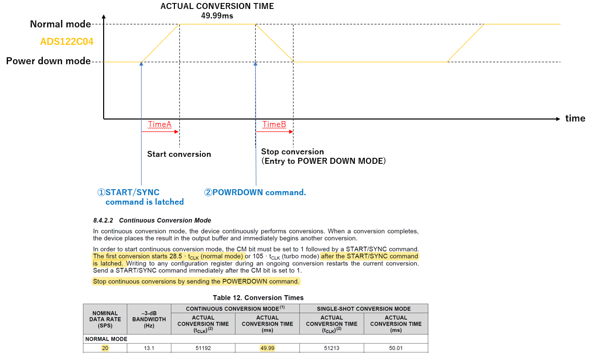
Therefore, we would like to operate ADS122C04 by START/SYNC and POWRDOWN command.
Please refer to the following Questions and Figure.
[Q1]
We understand that If Data rate is 20SPS at CONTINUOUS CONVERSION MODE,
Time A in Figure is around 28us (28.5*tCLK(Normal mode)).
Is my understanding correct?
[Q2]
Could you please let us know TimeB in Figure(??us)?
[Q3]
Could you please let us know if you have any concern for my timing chart?
Regards,
Kanemaru


