This thread has been locked.

If you have a related question, please click the "Ask a related question" button in the top right corner. The newly created question will be automatically linked to this question.

ADS1299: ADS1299 - Bipolar Mode (+-2.5V) - Signal clipping due to faulty VREFP to VREFN decoupling?

Part Number: ADS1299

Hello together,

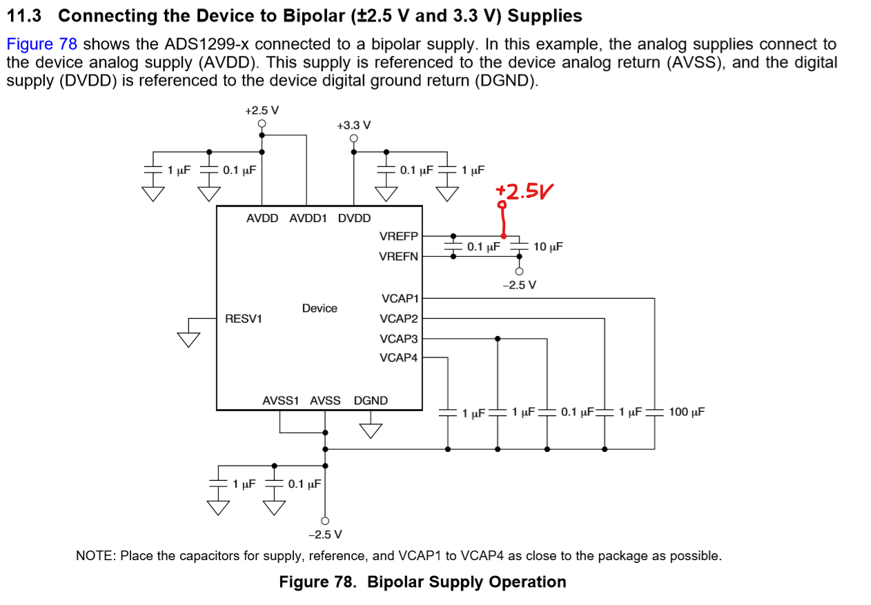
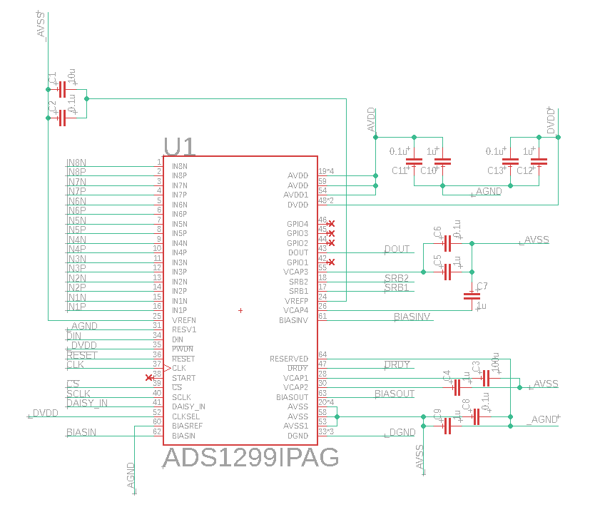
I buidl a custom board with several ADS1299 on it. During testing, internal Measurement works fine. When switching into a "normal mode", that is SRB1 to all cathodes and indivudal signals to each anode per channel, the signal is clipping into "0x7FFFFF" even though the signal apllied is in range -10 to 10 mV. Therefore I checked all power supplies (AVSS=-2.5V, AVDD=2.5V, DVDD=3.3V) and made sure, all AVSS/AVDD/DVVD are connected properly, so theres that. But I noticed, that VREFP is only decoupled to VREFN by two capacitors, as mentioned in the datasheet (11.3 Connecting the Device to Bipolar (±2.5 V and 3.3 V) Supplies). Is there a wire missing, which will connect VREFP to AVDD? (See proposal in red). If not, what am I missing

Greetings

  • Hello Mavin,

    Thanks for your post and welcome to our forum!

    The ADC reference voltage is generated internally by default. This is a precision internal bias voltage that is less than the supply, so it will not be equal to AVDD. You should be able to probe across the external decoupling capacitors and measure 4.5 V (VREFP - VREFN) to confirm the reference is operating correctly.

    Can you please share the complete register settings that are used for internal test signal measurements and normal input measurements?

    Best regards,

  • Hi Ryan,

    I will check in Detail on Monday, when I am back at work.

    But as far as I can recall, I measured -2.5V on VREFN and -2.48V (something a little higher than 2.5V, but not significantly) on VREFP, in respect to AGND.

    For the internal Registers, everything is kept on default for internal measurement, as it is after a reset or power (see 9.6 RegisterMaps -> Table 11 -> Default Settings). The only exception is CLKEN=1, as another ADS1299 is powered by that clock. But both are up and running after enabling CLKEN, as I can read the measurements from all channels through daisy chain.

    For the "normal mode", all channel registers are set to CHnSET=0x60, which is also the default value, except the MUX. Additionally, SRB1 is also set to 1 to be the common reference for all channels.

    Greetings

  • Si I checked again: VREFP - VREFN is 6mV on device 1 and 15mV on device 2. I also checked. I also checked all other nets again, and each one is nominal (AVSS=-2.48V, AVDD=2.5V, DVDD=3.3V, AGND=DGND)

    Greetings

  • Hello Mavin,

    The internal reference buffer is powered-down by default. Please follow the Initial Flow at Power-Up diagram illustrated in Figure 67 of the data sheet.

    Regards,

  • Hi Ryan,

    thats the answer to my problem! Cannot understand how I missed that...

    Thanks for your patience.


    Greetings