This thread has been locked.

If you have a related question, please click the "Ask a related question" button in the top right corner. The newly created question will be automatically linked to this question.

ADS1120: Two two-wire RTD configuration. It's possible?

Part Number: ADS1120
Other Parts Discussed in Thread: ADS1220, ADS114S06

Hi,

I'm wondering if it is possible to attach two two-wires RTD sensors to ADS1120 in ratiometric measurement, with reference resistor in low side?

I have seen the "Basic Guide for RTD Measurement - SBAA275" , and the pin sourcing the current does not take any measurement.

I´m in a space constrained application, so i want to use ADS1120 to hook up two two-wire RTD.

Thank you.

  • Hi Fernando,

    welcome to our forum and thanks a lot for your interest in our ADS1120.

    We wrote the following TechNote which describes how two 2-wire RTDs could be measured with an ADS1120 (the example uses the ADS1220 which is the 24-bit version of ADS1120):
    Low-Cost, Single-Chip, Diff Temp Measurement Solution Using Delta-Sigma ADCs

    For the solution to work we had to place the reference resistor on the high side though.
    Also the two RTDs had to be placed in series. Means if one RTD is disconnected, you lose the information on the other RTD as well.

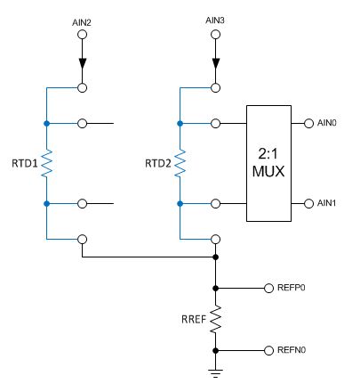
    If you need to place the reference resistor on the low side and don't want the RTDs in series, then you will need an external Mux.
    You could e.g. connect one or the other RTD to AIN0/AIN1 using the Mux and route the IDACs to the RTDs using AIN2 and AIN3. The low side of the RTDs would be connected together and fed to the reference resistor. Only one IDAC would be active at a time. See the drawing below (it shows 4-wire RTDs but the principle is the same):

    Another option would be to use ADS114S06 which offers more analog inputs than ADS1120.

    Regards,

  • Hi Joachim,

    First of all, thanks fou your fast support. I'm glad to see the TI's TechNote about this particular application with the same IC that i'm planning to use.

    Well, i did a drawing tonight after reading the TechNote. Also, i have followed the steps discribed in the TechNote about "selecting component values and ADC Settings".

    Here is my results:

    Parameter Unit Value
    Temperature Sensors PT-100
    Temperature Measurement Range °C -20 to 140
    Resistance Range Ohm 92.16 to 153.58

    - Max temperature to measured = 140°C (153.58 Ohm)

    - Operating voltage = 3V

    - Rref = 4x 153.58 Ohm = 614.32 (sure, i need to round to the next commercial value)

    - IDAC current = 1 mA

    - IDAC voltage (considering Rref, RTD1 and RTD2 stacked together in their maximum values = 921.48 ohm) resulting is about 0,922V, that still meets the IDAC's compliance voltage;

    - Gain = as same 4x factor chosen in Rref (internal PGA bypassed).

    schematics

    So, my questions is: 1) how to determine the resolution in °C of this system ? 2) the wiring schematics is correctly ?

    In a few words, how can i know if i'm using all the available room (range) of the ADS1220 ADC ?

    Thanks again.

  • Hi Fernando,

    I am glad the document was helpful.

    Your circuit looks fine to me.
    Regarding your IDAC and RREF values. One additional constraint we have to pay attention to is the minimum required reference voltage of 0.75V across RREF (see table 63. in the ADS1220 datasheet).
    As we have enough IDAC headroom left we could simply increase the IDAC current to 1.5mA if power consumption is not a key concern for you.
    A larger IDAC current does in general also yield a better temperature resolution.
    As we are limited to Gain=4 in this circuit implementation, those settings (IDAC=1.5mA, RREF=~620Ohm) are the most optimum I can think of.
    You could increase the current to 2mA by routing both IDAC1 and IDAC2 to REFP0 and setting them to 1mA each.
    Increasing RREF further will not provide any benefit.

    Are you asking about temperature resolution in °C or rather temperature measurement accuracy in °C?
    To estimate the resolution you first need to look up the input referred noise (en) of the ADS1220 in the datasheet tables 3 or 7. The lower data rate you select, the better the resolution will be.

    Temperature Resolution = en / (I_IDAC x RTD_Sensitivity)

    Example using Gain = 4, Normal Mode, DR = 20SPS, en = 3.9uVpp, I_IDAC = 2mA, RTD_Sensitivity = 0.385Ohm/°C
    Noise-free Temperature Resolution = 3.9uVpp / (2mA x 0.385Ohm/°C) = 0.005°C

    Regards,

  • Hi Joachim,

    Thanks again for your clearly explanation. Now i fully understand .

    I will finish the PCB layout and test.

    Thank you.