This thread has been locked.

If you have a related question, please click the "Ask a related question" button in the top right corner. The newly created question will be automatically linked to this question.

ADS7883: ADC minimum clock frequency

Part Number: ADS7883

The datasheet defines the characteristics of the ADS8873 at 32MHz and 48MHz clock frequencies. Are these the maximum clock values or the can the device work at lower frequencies, and lower sampling rates) as well? I tried with lower frequencies, e.g. 8MHz, but my results are inconsistent

Thank you

  • Hello,

    The ADS7883 can work up to either 32 or 48 MHz given the Vdd supply. these means that the device does support lower clock frequency (in other words slower sampling rates). As long as the timing requirements on page 4 of the datasheet are met, the device should work correctly.

    What inconsistencies are you seeing? I would suggest using an oscilloscope and probe the digital lines, CS, SDO, SCLK, to make sure that the lines are behaving as expected and to verify timing. please share these as well

    Are you not seeing these inconsistencies at the max rate but are seeing them at lower sampling rates/clock frequencies?

    Regards

    Cynthia

  • Hello Cynthia,

    thank you for clarifying. I thought it was a problem of frequency so I increased it.  This is my setup: an FPGA eval board implements SPI Master; a DC power supply powers the ADC Eval board, the AC signal to be converted is provided by a signal generator. Signal generator, FPGA board and ADC board share the same ground.
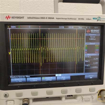
    The SDO from the ADC board seem to be noisy, as in the attached picture. I see this even if there is no input to the ADC and I am expecting all zeros.

    I can see the clock and CS from the FPGA clearly, as in this screenshot

  • Looking at this, I think there might be a set up issues. The Scope shows SDO going below ground, which it is not capable of.

    The SDO should change at the same frequency as the clock.

    For debugging purposes, use a DC input, or ground the inputs. This way we can compare what we expect the SDO to be vs what it is.

    try to make the connections between the boards as short as possible, this will help with noise

    Would you probe all three digital lines on the oscilloscope?

  • Ok I shortened all the wires between the FPGA and the ADC board and checked the connections and made sure the input is grounded.

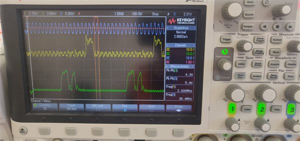
    These are the analog signals -blue CLK, yellow CS, green SDO- Please note that they have different scales, and are shifted vertically to make them visible. However, the SDO doesn't go below ground any more

    I see the same type of output from the SDO both with signal (sine or just DC voltage) and without input.

    These are the digital signals from the digital analyzer, the SDO gives random values, while I expect either all zeros (no input) or constant values (DC input)
     

  • These signals look really bad. Note the clock looks really bad, and goes below ground.

    But in general, it looks correct. Notice that the first two falling edge of SCLK after CS falling edge will be zeros, then the data, 12 bits, and then 2 more zeros.


    Also, when the input is floating on the ADC, meaning nothing is connected to it, this does not meant you will get all 0 every time.

    Let's try the following.

    Can you separate the FPGA board from the ADC, and use a signal generator to test the ADC. This will very that it is the ADC, and not the FPGA. you should also check the signal from the FPGA to make sure those are correct. when not connected to the ADC.

    Use a 1V DC input. the output should be  0011 0011 0011, but with the extra zero padding it will be 0000 1100 1100 1100

    You can do just one frame to test this, instead of continuous clocks and CS signals.  you can also try slowing down the clock frequency, to get a cleaner signal

    Regards

    Cynthia 

  • Hey, thank you for your help.

    I disconnected the FPGA and used an Arduino instead that has slower clock and cleaner SPI signals. I gave 1V DC with the signal generator, and I almost got the sequence. In fact I have 0000 1100 1101 1100 as in the picture


    But before I proceed, can you confirm that the clock CPHA=0 is correct? Or should it be on trailing edge (CPHA =1?). I was playing around with the variable resistor  R13 so I might have changed the reference value.
    So what voltage should I see on TP5 normally? (please note that I am not using my reference voltage) 

  • The SDO data should be sampled on the rising edge of SCLK, thus  CPHA =1 is correct


    Notice that if SCLK is low when the falling edge of chip select, then CS falling edge will be considered as the first SCLK falling edge

    Regards

    Cynthia