This thread has been locked.

If you have a related question, please click the "Ask a related question" button in the top right corner. The newly created question will be automatically linked to this question.

DAC8771: buck boost design when Current output only for DAC8771

Part Number: DAC8771
Other Parts Discussed in Thread: TIPD216

We have a application for current output only for DAC8771.

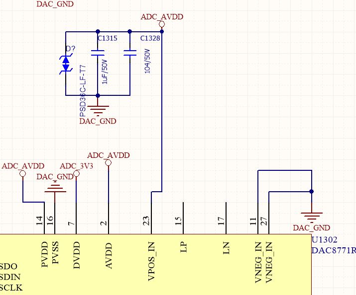
As the picture below, AVDD will be 24V.

is this topology workable for current output only?

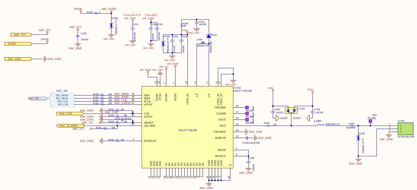
Same question as above. is this circuit also workable for out application?

if the answer are yes for both of these two.

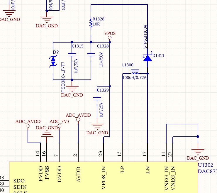
What is the difference between these two circuit. i'm not fully understand what the buck boost used for in DAC8771 

  • Hi Albert,

    The figures on page 66 and 67 attempt to articulate how to configure the device for each dual-supply w/ internal DC/DC, single-supply w/ internal DC/DC, and external supply options. I apologize if those diagrams are not clear but it does look like you have drafted accurate schematics for both single-supply w/ internal DC/DC and external supply use cases.

    The DC/DC is used for optimizing thermal and power dissipation of the current output. Essentially if you were to use a static supply for a high-side current source (nominally 24V as you have mentioned here for PLC current outputs), there is the potential for excessive power dissipation in the output PMOS depending on the magnitude of the load impedance. For example, with a 1 ohm load virtually all of the power is dissipated in the output stage of the DAC.

    What the DC/DC offers is to buck that 24V high-side supply down to a lower voltage, as low as ~4.7V for the DAC8771. If we got back to the example with the 1 ohm load, the DAC8771 would expose the output PMOS to just 4.7V instead of 24V and dramatically reduce power / heat.

  • i would use 4-20mA only, so i would use single-supply.

    is it make sense?

    why can't i supply 5V directly to AVDD, so that would not make the excessive power disspation in output PMOS when  the magnitude of the load impedance?

    what would be impact when AVDD lower than 12V?

    sorry for the question may not make sense.

  •  Hi Kevin

    Could you help to confirm whether the circuit is fine or make some suggestions.

    Especially, the portion of protect circuit .

    the application is 4-20mA out put only

  • Albert,

    Generally speaking the PLC modules that I have seen only specify a maximum load impedance and it is usually on the order of 1 kOhm, occasionally a bit smaller maybe around 625 ohms. Assuming 20mA full-scale output current and 2V compliance voltage headroom, that means a high-side supply of at least 22V is required for the 1 kOhm load case and 14.5V for the 625 ohm case.

    Since the PLC datasheet only specifies a maximum load and a short-circuit is a valid load condition for a current output, it is possible to see smaller loads in some use cases. The typically problem, however, is that the PLC was designed to drive much larger loads and the conventional solution does not include any active control of the high-side supply voltage - so it's possible to run into this heat problem which is basically what the DAC8771 was designed to solve.

    If you just used a 5V supply, once again assuming 2V compliance voltage headroom for the current source, you would only be able to drive up to 150 ohms. In the case of DAC8771, as you seem to have noticed already, the minimum AVDD is 12V - which would accommodate up to a 500 ohm load.

    If you were to use a supply voltage less than 12V essentially the datasheet would become invalid in terms of providing any of the same functional or parametric guarantees. This could be something simple like a reduced maximum output voltage from the DC/DC or, depending on how low the supply is actually reduced, something more severe like the device not powering up correctly or loading incorrect OTP values which would basically degrade the analog performance.

  • Albert,

    I apologize - my previous reply seems to have been delayed to actually appear on the forum.

    Concerning this new question, could you please clarify exactly what conditions you need to protect the system from? This is a cornerstone to any protection suggestion.

  • Hi  Kevin

    Apologize for the lack of information.

    We would like to protect the system from EFT 1KV ,Surge test 1KV (common mode) and ESD test.

  • Albert,

    Sorry - I was out of office on international business travel.

    I would suggesting taking a look at TIPD216:

    http://www.ti.com/tool/TIPD216