This thread has been locked.

If you have a related question, please click the "Ask a related question" button in the top right corner. The newly created question will be automatically linked to this question.

ADS1299EEGFE-PDK: How can you remove powerline noise when collecting ECG data?

Part Number: ADS1299EEGFE-PDK
Other Parts Discussed in Thread: ADS1299, ADS1298

I am Lead I ECG with the ADS1299. I have three electrodes connected to the board with the following configuration:

  • LA - > CH1 +
  • RA -> CH1 -
  • RLD -> JP17 (Right Pin)

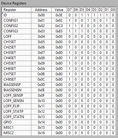
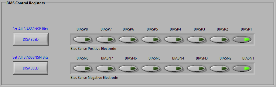
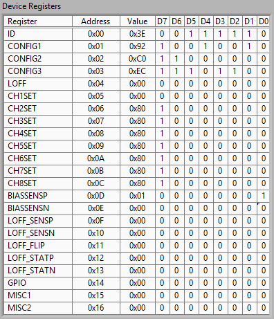
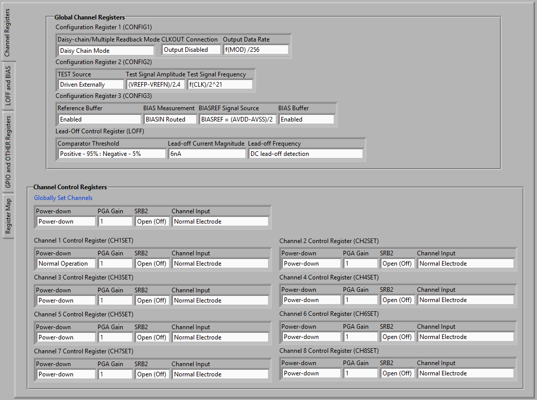
I have configured the ADC registers like this:

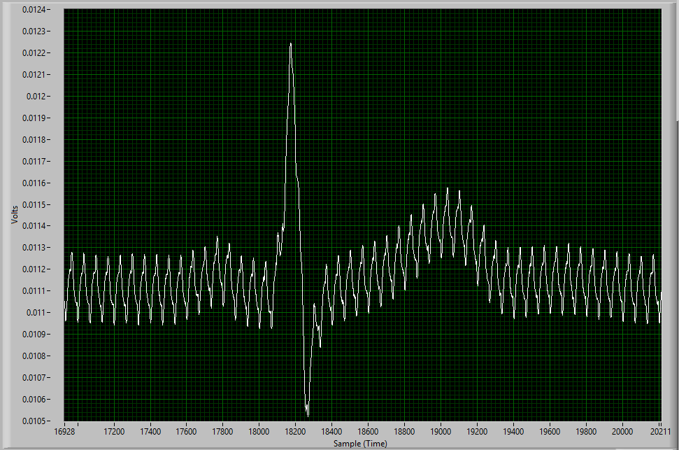
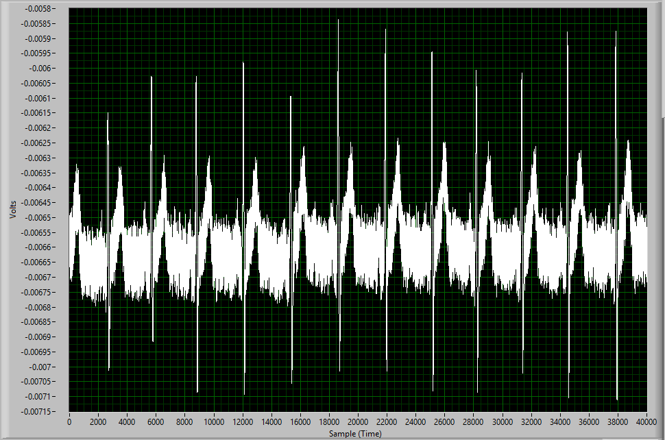
While the signal does look okay and clearly shows the QRS complex it is very noisy.

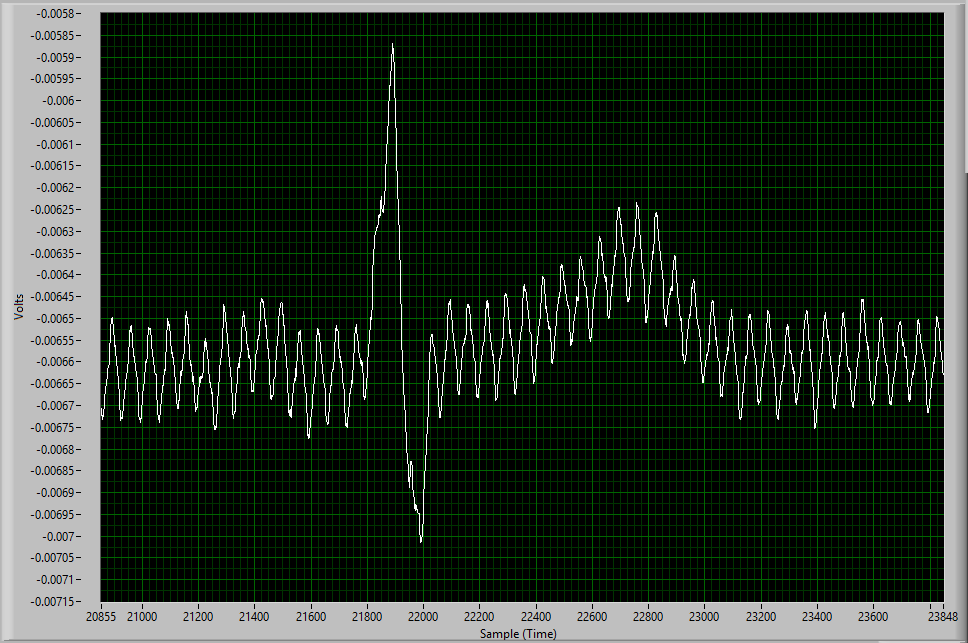
If I zoom in on one beat you can clearly see the HFN

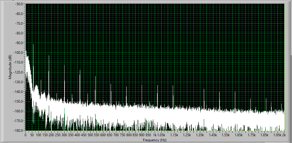
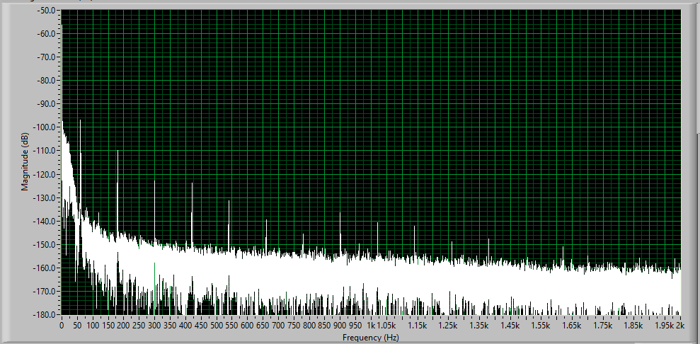
I believe that this HFN is powerline noise and the FFT of the signal seems to support that hypothesis.

I want to know if it is possible to remove it in the analog domain. I know that I can use some kind of LPF in post processing but I'm concerned about introducing a delay.

  • Hello,

    50 Hz and 60 Hz power line interference is a common challenge in biopotential applications. There is an application note about how using the RLD improves common-mode rejection of this noise linked in our ADS129x BIOFAQ help page. Using shielded ECG cables with the shield driven to the same common-mode as the body can help reduce noise coupling as well.

    Can you share the complete register map table? It's found under the last tab.

    Best regards,

  • Hi Ryna,

    I have taken a look at the ADS129x BIOFAQ before and that's how I knew to use the RLD to help reduce noise. I don't think the ECG cables I'm using are shielded but I can wrap them in foil if you think that will help.

    Here is my register map:

    Do you think this is something we can resolve?

  • Hello,

    Based on the register settings above, you are only applying a buffered DC mid-supply voltage to the RLD electrode. The RLD amplifier is not sensing the common-mode voltage at the outputs of the PGAs. More importantly, the RLD amplifier is not powered on. Please review sections 9.3.1.7.6 and 10.1.1.2 in the data sheet.

    Using properly shielded coaxial cables with the shield driven to the same common-mode voltage as the electrodes will help reduce the parasitic capacitance between the shield and the electrode wires, thus reducing the 60-Hz noise coupling. Shielding the ECG circuit board will have the same effect.

    Best regards,

  • What data sheet are you referring to? This data sheet does not have those sections and I couldn't even find the world RLD amplifier when I searched the document.

    Is it possible to just tell me what changes I need to make in the Evaluation Software? Should I be enabling something under the LOFF and BIAS tab?

  • My apologies - as we were discussing ECG electrodes and RLD techniques earlier, I gave you the section numbers for the ADS1298 data sheet. The ADS1299 uses the same features for biasing the biopotentials on the body, but we refer to this electrode as the "BIAS" instead.

    In the CONFIG3 register (60h), you will need to enable the BIAS amplifier and the internal mid-supply BIASREF voltage by writing 0xEC. Also, you will need to select the input electrodes for the common-mode derivation. This is done in the BIAS_SENSP (0x0D) and BIAS_SENSN (0x0E) registers. As you are using IN1P and IN1N only, you can write 0x01 to both of these registers.

    Sections 9.3.2.4.5 and 10.1.2.2 provide more details about configuring the BIAS amplifier.

    Best regards,

  • Thank you for clearing that up and helping me properly configure the registers.

    I'm just running into 1 issue and I'm unsure if I am doing something wrong or if there is an issue with the Evaluation Software.

    I turned on the BIASP1 and BIASN1 registers but when I check the register map it still shows up as 0.

    Is this just a display issue or is there something else that needs to be changed? Also, is it possible to configure the registers without using the GUI? I think that would make this much easier.

  • I don't think you're doing anything wrong, but this might be a bug in the GUI. I'll try to confirm in the lab on Monday. In the meantime, let me know if the results improve at all with IN1P selected. The "Set All" buttons you see on the left should still work for both BIAS_SENSx registers, but my concern is that selecting too many inputs will increase the BIAS amplifier gain too much and saturate the output (the gain at DC is set by Rf / (220k || 220k ||...) for each electrode selected.).

    Best regards,

    Ryan

  • It didn't seem to make any difference so that's why I was wondering if I was configuring the registers incorrectly.

    This signal still has the same HFN\

    And more importantly the FFT still shows the 60 Hz noise

    I also tried the select all button for both the BIASP and BIASN switches with no noticeable change. If there is a way to configure the registers without the GUI I can try that to confirm.

    I have also been looking at this guide on how to remove powerline noise and with the exception of the Faraday cage I have tried everything on that list. So I'm wondering if removing that HFN is possible.

  • Thanks for trying those different options for deriving the BIAS common-mode signal. At the end of the day, the BIAS feedback can help suppress the common-mode noise only so much. It does this by reducing the amplitude of the common-mode noise closest to the signal source (i.e. where it couples onto the body). This, in turn, reduces the amplitude of the signal that converts from common-mode to differential.

    It's still possible that the 60-Hz noise is coupling elsewhere in the system or somewhere further along the signal path. The only way to identify this is to systematically short the inputs together as various places along the signal path and see where the noise becomes a problem. Start inside the device with the MUX set to input-short, then progress to an external short at the pins, then an external short before the R-C filters, then the input connections to the board, and finally, the electrodes themselves.

    Other suggestions:

    1. Replace the signal source with a function generator, making sure the grounds are shared between the equipment and PCB ground.
    2. Reduce the ADC bandwidth to filter out the higher 60-Hz harmonics.Currently, you are sampling at 4kSPS.
    3. Implement a 60-Hz notch filter in DSP.

    Best regards,