I am using an afe5808a as the receiver and when i transmit a single sine wave (+-) the adc works ok.
When I start to increase the number of cycles the adc starts to go flaky, especially at a lower input impedance. This takes a long time to recover ( on the order of hundreds of microseconds). and makes subsequent transmit receive cycles impaired as well. This is making it very dificult to process cfd/pw data and even bmode lines between/after the cfd are being corrupted, as it takes so long to recover.
It seems to be the pga getting overloaded and clamping but its often just warping the signal causing stability probems for any imaging.
During transmit on the backside of the tx/rx switch, the signal amplitude only gets to about +/-0.8v ( 1.6pp)
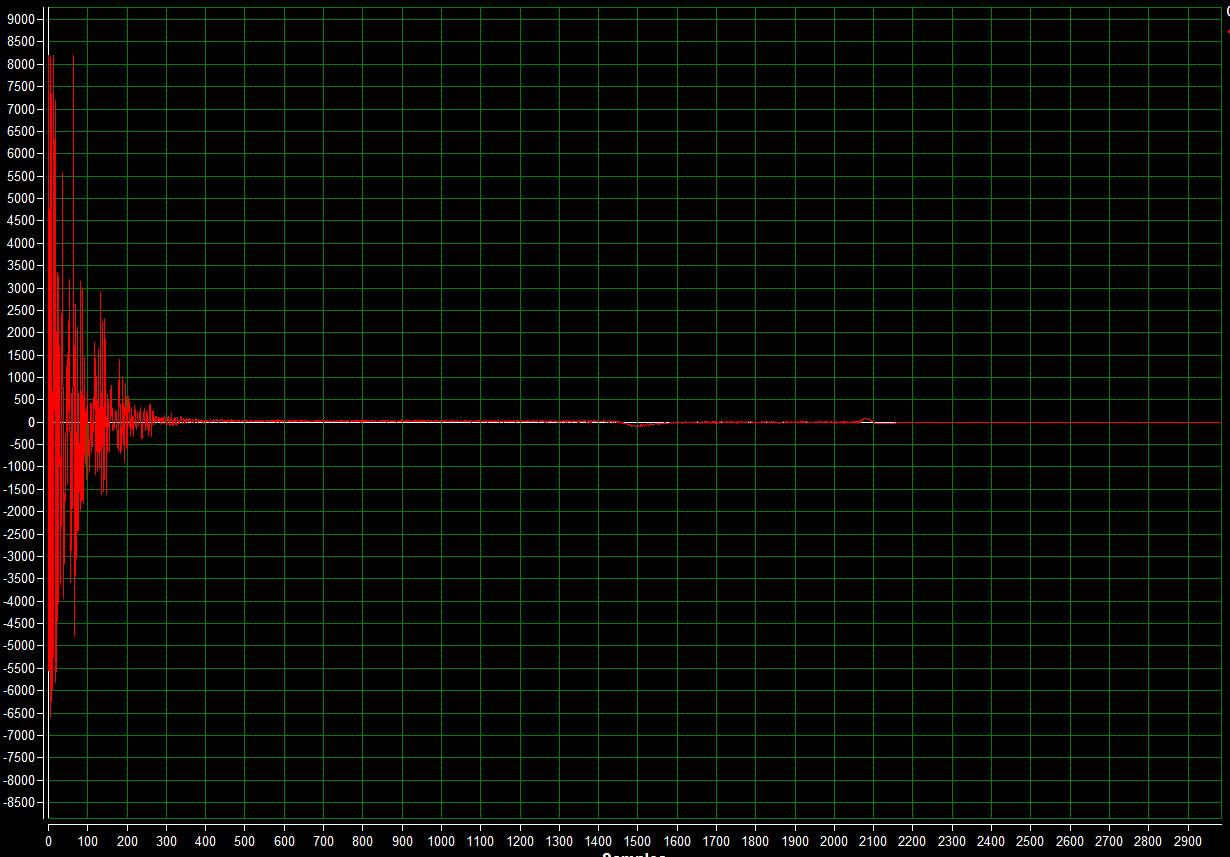
This is looking at the adc output on a single channel tx/rx at 1 cycle(+-)
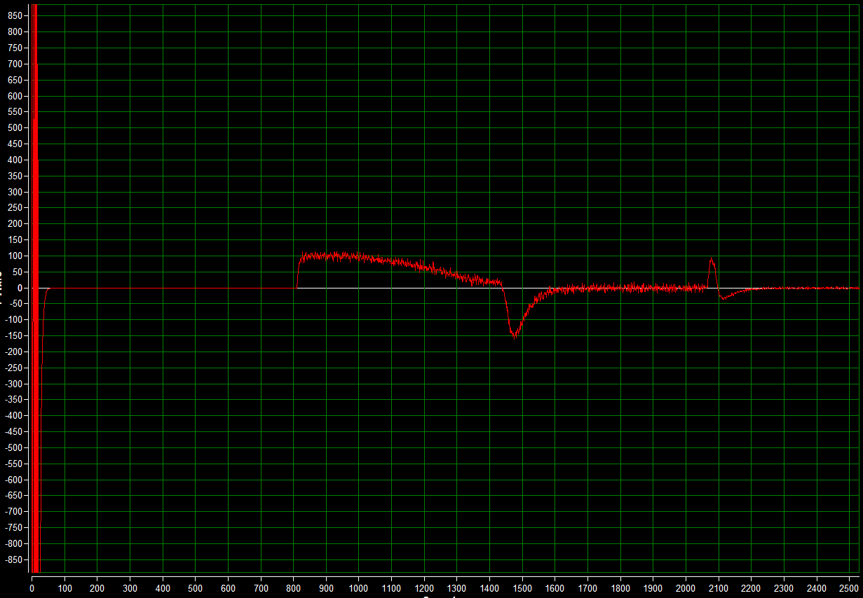
then looking at the same channel while transmitting 3 cycles (+-+-+-) zoomed in
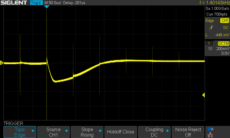
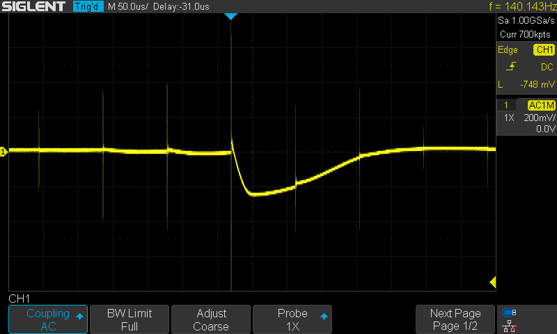
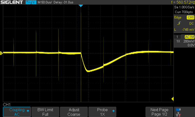
When I scope the lines I can see the input get pulled down pretty hard. The spikes are the transmit signals from running the active tx/rx pair across an array.
this is looking between the schottkey diodes and the input decoupling cap. it takes about 200us to stabilize. these droops are about -300mv
backside of the act cap
backside of the input cap.
ive got the lna at 24db, pga at 30db, vcat at 0db attenuation, pga clamp at -2db, lna clamp at 1.5.
taking the pga gain down seems to help but it is still not stable and still has large gaps in the adc output values like above. It does seem to be the pga getting overloaded but changing the clamp doesnt help. taking the gain down through the vcat helps but then i lose penetration. i use the dig tgc for cfd and cant really change that halfway down the acoustic line which means im either stuck with an unstable signal or not enough penetration.
taking the input impedance up to 500ohms helps but still is unstable and has gaps in the data.


